background image


Date 

9/7/2018 

File 

BSR-2114/MAR 

Document Number 

921211401_09_002 

Page 

 46 από 74 


46 


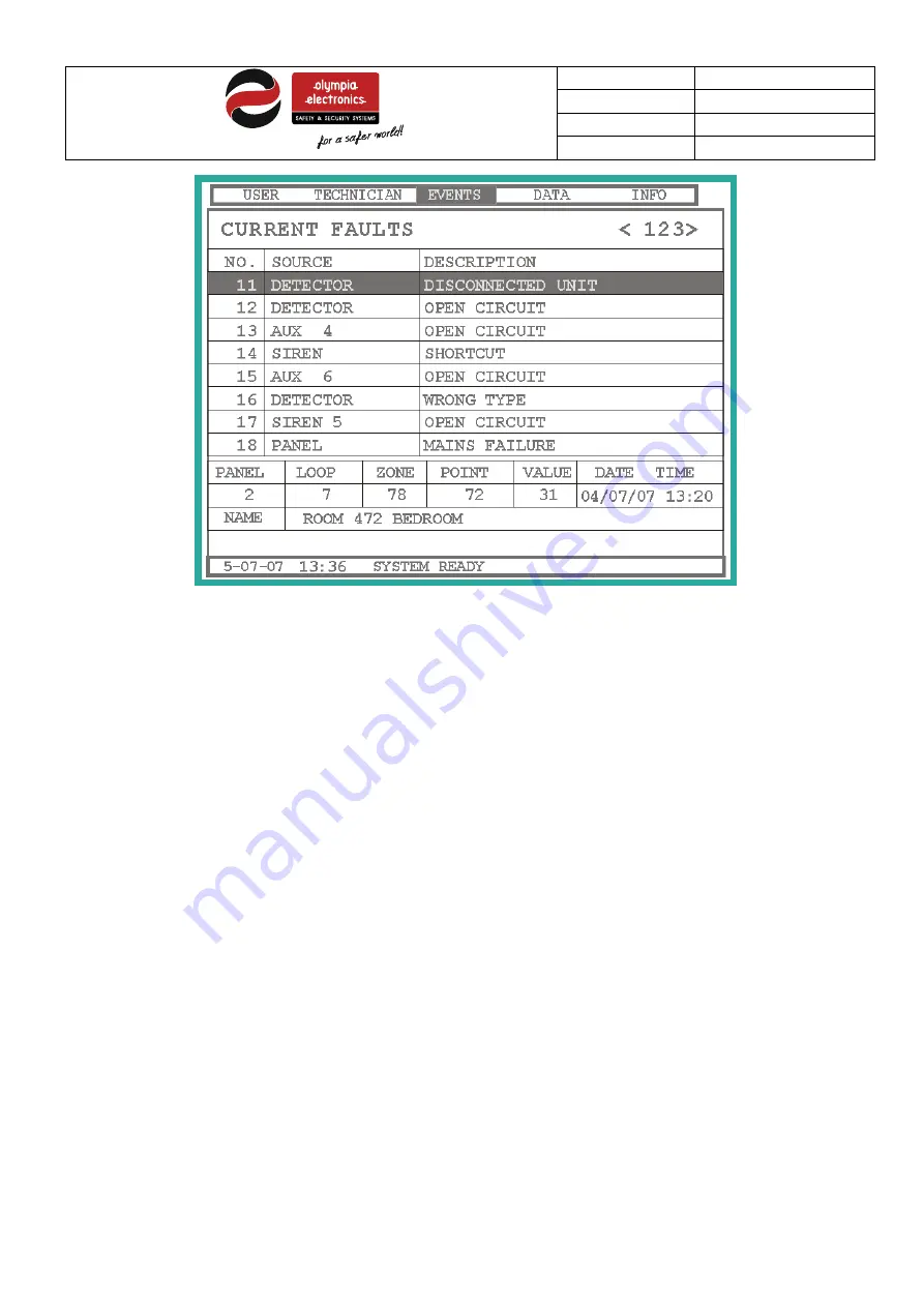
Figure 4-19 Viewing events 


Beside the title we can see the total amount of event of the type selected. 
The top section is divided into 3 sections, the general number of the event, the origin of the event and finally the description 
of the event. The lower section shows details of the event that we have selected to view ( black bounds).  
In our example the panel informs us that the sensor of panel 2, loop 7, zone 78 with address 72 is not connected. Additionally 
the name of the detector is displayed «ROOM 472 BEDROOM» 
 
To navigate to other items use the «

UP» or 

«

DOWN»

 keys or for faster scrolling use the 

«PAGE UP» or «PAGE DOWN» 

keys. 

 
Up to 500 events of each type can be logged. 


Содержание BSR-2100

Страница 1: ...BSR 2104 MAR BSR 2114 MAR Addressable fire detection panel with 2 or 4 loops and expansion capabilities Operation and installation manual...

Страница 2: ...ains power 230V AC 22 3 4 2 Battery connections 23 3 4 3 Connecting points to the loop 24 3 4 4 Connecting the sirens 25 3 4 5 Connecting panels to a network 26 3 4 6 Connection panel with repeaters 2...

Страница 3: ...relay 65 5 4 4 Task setup 65 5 4 5 Setup Groups 66 5 5 System menu 67 5 5 1 Automatic Point detection 67 5 5 2 Network detection 69 5 5 3 Extension detection 69 5 5 4 Initialize names 69 5 5 5 Factor...

Страница 4: ...ecting sirens to the panel 25 Figure 3 12 Connecting panels to a network 26 Figure 3 13 Repeaters connection 27 Figure 3 14 Fire Alarm Routing and Fire Protection connection 27 Figure 3 15 Fault warni...

Страница 5: ...relay testing 58 Figure 5 6 Activating the output 58 Figure 5 7 Siren testing 59 Figure 5 8 Network check 60 Figure 5 9 Point configuration 61 Figure 5 10 Selecting the type of point 62 Figure 5 11 Ch...

Страница 6: ...Page 6 74 6 Table index Table 3 1 Device consumptions 29 Table 3 2 Loop cable length 30 Table 3 3 Siren cable length Alarm 31 Table 6 1 Factory default settings 72 Table 6 2 Options with requirements...

Страница 7: ...loop Each loop can accept various types of points We will refer to these points later on in the manual The panel has 96 zones and is suitable for larger installations such as malls shopping centers h...

Страница 8: ...lections that are used to control the panel see paragraph 1 3 2 The panel also has a safety lock and a thermal printer mounting point see figure 1 1 1 3 2 Panel Keypad Figure 1 2 Panel keypad 1 Buzzer...

Страница 9: ...se of a power line failure 9 Battery During a problem with the battery 10 Fault Disable yellow Zone Blinks during a zone error Stays always on to indicate disabled zones 11 Fire routing Blinks to indi...

Страница 10: ...r status indication LED 4 Paper compartment To advance the paper press the button 1 located on the top right side of the printer When the printer is connected correctly then the green LED 3 is ON When...

Страница 11: ...t PREALARMS When this indication is shown then there are pre alarms in the system DELAYS ON When a delay of an output is activated PC During this indication there is a communication between the panel...

Страница 12: ...Quiescent state Alarm C Pre Alarm D Fault 2 2 Quiescent state The state where there is no alarm pre alarm or a fault condition is called the quiescent state The LCD will be approximately identical to...

Страница 13: ...election When the panel is in quiescent state then the language can be changed by pressing the ESC key After pressing the key the following language selection screen is shown Figure 2 2 Language selec...

Страница 14: ...ents Alarm counter is shown to the right of the window title The screen is divided into 2 sections The upper section shows the first alarm event along with the date 05 07 07 time 13 41 name of the poi...

Страница 15: ...of the point the issued the pre alarm and finally the type of point The lower section shows the last pre alarm event that took place When a pre alarm is issued the internal buzzer will sound periodic...

Страница 16: ...indications during the fault state The total number of fault events Fault counter is shown to the right of the window title The screen is divided into 2 sections The upper section shows the first fau...

Страница 17: ...by pressing this button 3 we can conduct a lamps test which will light all the leds and the display in order to verify for good operation 2 7 Access Level 2 User Functions This level contains all the...

Страница 18: ...nput output unit with auxiliary relay BSR 5032 MAR Addressable siren with beacon BSR 5032 WP MAR Waterproof Addressable siren with beacon BSR 7070 MAR Addressable line isolator Does not register as po...

Страница 19: ...ssor board the zone indicators the printer mounting area and the lock of the cover 2 The right internal section contains the power supply the loop board the input output board the battery compartment...

Страница 20: ...r connecting sirens for connecting the loops and for connecting the mains power supply The diagram below shows the connection terminal blocks of the board Figure 3 2 Loop board 3 3 2 Input Output boar...

Страница 21: ...nsion Rela y6 Relay6 R elay5 R elay5 Relay5 Relay4 Relay4 Relay4 Other Outputs External device power supply Figure 3 3 Input Output board Extension Output Loop Output Other Outputs Panel Interface Ext...

Страница 22: ...rd as shown in figure 3 5 Below the terminal block there is a fuse with a rating of 5x20 2A 250VAC SLOW which is the central fuse of the panel Figure 3 6 230VAC connection terminal Warning 1 During th...

Страница 23: ...connected to the poles of the battery The black cable connector is connected to the negative battery pole it is marked with a or is colored black and the red cable with white connector is connected to...

Страница 24: ...ing the batteries The metal brackets must be fitted at all times 3 4 3 Connecting points to the loop The diagram below show a typical connection between points and the loop Figure 3 9 Connecting point...

Страница 25: ...th external LED Connection with L of the loop Ceiling mounting positions R L L L L Figure 3 10 Connecting a sensor base to a loop Warning To overdrive the delays at access level 1 a call point must be...

Страница 26: ...n up to 32 panels Figure 3 12 Connecting panels to a network The maximum distance between 2 panels must not exceed 400m If it is required to exceed this distance then an A 485 which is a RS 485 protoc...

Страница 27: ...ted to the chassis of the panel Figure 3 13 Repeaters connection 3 4 7 Fire alarm routing and fire protection connections The panel has provision of Fire Alarm routing and Fire Protection routing outp...

Страница 28: ...fently to default setting but then they will not fulfil the EN 54 2 3 4 9 Various other connections The panel also has the following available outputs Input Output board Extension A A terminals These...

Страница 29: ...tectors 1 1 2 150 BSR 6060 MAR Heat of Rise detector 1 1 2 150 BSR 5036 MAR Call point 1 1 2 150 BSR 7070 MAR Line isolator 2 4 32 BSR 7071 MAR Line isolator 10 10 4 BSR 8017 MAR Input Output unit 1 1...

Страница 30: ...igure 3 17 Calculating loop consumption with a PC In order to fully understand this we will explain it with an example In a 70 room hotel we will use a BSR 2100 panel Each room has a smoke detector an...

Страница 31: ...ove the grommets in order to not change the protection class IP30 of the cover required by regulations EN 54 2 Each connection should have it s own cable for example for connecting the loop or the sir...

Страница 32: ...To properly install a loop to the panel adhere to the following guide lines 1 The maximum number of devices that can be connected to a loop is 150 In this case the connection cable must be at least 1...

Страница 33: ...ion This section will reference all the function that can be obtained using access levels 1 and 2 To enter the menu press the ENTER key when in the main screen figure 4 1 Figure 4 1 Main screen After...

Страница 34: ...contains information about the system that can be accessable by any user To select a menu navigate to the menu using the keys LEFT and RIGHT and press the ENTER key We will continue in detail of all t...

Страница 35: ...ge 35 74 35 Figure 4 4 User Code After entering the correct code press the ENTER and the submenu will be shown as the figure below Figure 4 5 User Menu As shown in the diagram The user can choose from...

Страница 36: ...ES DATE TIME SHOW DISABLED SEGMENTS POINTS FOR SERVICE ALL SYSTEM LOOPS POINTS ZONES AUX RELAYS SIRENS ALL SYSTEM LOOPS POINTS ZONES AUX RELAYS SIRENS OF POINTS AUX RELAYS OF SIRENS TASKS GROUPS TIME...

Страница 37: ...elays do you want to enable SIRENS Select 1 of the 8 sirens that you want to enable Respectively in the disable menu we have the same selections as the enable menu but now we can use them to disable e...

Страница 38: ...Over this value the device will issue a pre alarm ACTIVATES THE ZONE When a sensor is activated then the respective zone is also activated ACTIVATES THE GROUP When a sensor is activated then the resp...

Страница 39: ...hen one is activated then all the others are activate too When we select Groups then a small window opens prompting the user to enter the number of the groups from 1 to 96 After that a new window open...

Страница 40: ...the system DAY ADJUST Adjust the day of the week of the system WORKING HOURS Adjust the working hours for the option DAY or NIGHT WORKING DAYS Adjust the working days for the option DAY or NIGHT In t...

Страница 41: ...e detectors are less sensitive and during the night the sensitivity increases 4 2 4 Show Disabled Segments menu Using this menu we can see which items are disabled as shown in the figure below Figure...

Страница 42: ...f detectors that are due for maintenance The top section is divided into two areas The left area is the general number of the detector whereas the right area contains the name of the detector The bott...

Страница 43: ...ss level1 also permits the user to view current and logged events that are categorized While in the main screen press the ENTER key Figure 4 15 Main screen in quiescent state Next press twice the righ...

Страница 44: ...EALARM EVENTS FAULT EVENTS ALARM EVENTS PREALARM EVENTS SHOW ALARM IN ZONES UNDER TEST SHOW FAULTS IN ZONES UNDER TEST SHOW ALARM COUNTER CLEAR EVENT HISTORY Figure 4 18 Events menu diagram The option...

Страница 45: ...ed pre alarm events if available Using the UP and DOWN keys we ca navigate through the events Pressing the ESC key exits this menu and goes to the previous SHOW ALARMS IN ZONES UNDER TEST If we press...

Страница 46: ...the event and finally the description of the event The lower section shows details of the event that we have selected to view black bounds In our example the panel informs us that the sensor of panel...

Страница 47: ...e data transfer between the panel and a PC Before making a transfer be sure to connect the panel with the PC via the USB port After that the port setting must be adjusted on the PC Figure 4 20 Compute...

Страница 48: ...ect via the Communication menu the option to send or to receive data to the PC Then select the DATA menu of the panel A code requester will pop up requesting the user to input a code Input the code fo...

Страница 49: ...el from the PC 4 4 1 Sending data to the PC When selecting the option TO PC a window is opened that shows a communication test between the PC and the panel Figure 4 24 Establishing communications As s...

Страница 50: ...d press any key to close the window 4 4 2 Receiving data from a PC When selecting the option FROM PC you must enter the technician code and after a window is opened that shows a communication test bet...

Страница 51: ...re 4 27 Information menu Figure 4 28 shows a flow diagram of the menu Figure 4 28 Information menu diagram In the first selection SYSTEM we can see information about the system figure 4 28 The choice...

Страница 52: ...ber of points connected to the panel CONNECTED PANELS IN NETWORK Shows the total amount of panels connected to the network PRINTER If a printer is available ETHERNET Shows if there is a capability to...

Страница 53: ...firmware and hardware versions of each loop as shown below Figure 4 31 Loop information If we select the TECHNICIAN option then we can view information regarding the technician figure 4 32 The techni...

Страница 54: ...Date 9 7 2018 File BSR 2114 MAR Document Number 921211401_09_002 Page 54 74 54 Figure 4 32 Technician information Press any key to close the screen...

Страница 55: ...used also to get access to the options that program the panel Due to these fact an access code is required The Access level 3 code is Figure 5 1 Access code for level 3 5 2 Technician menu If we selec...

Страница 56: ...ME TECHNICIANS INFO DISABLE BUZZER CHANGE LANGUAGE SCREEN BACKLIGHT SETUP NETWORK SIRENS NETWORK EXTENSION FACTORY DEFAULTS INITIALISE ALARM COUNTER MODE REPEATER F1 KEY SETUP STEP BY STEP ZONE ALL ZO...

Страница 57: ...ng from the loop and is the following TYPE The type of point on the loop VALUE The value that the point is reporting FLAGS meaningful only for the manufacturer CORRECT PACKETS RECEIVED Total amount of...

Страница 58: ...seconds every time a alarm occurs in zone under test THIS OPTION IS NOT ACCORDING TO EN 54 2 5 3 3 Check Auxiliary relay menu With the option we can test the good operation of the 6 auxiliary relays...

Страница 59: ...low shows a typical screen for testing one siren Figure 5 7 Siren testing The screen shows us the settings of the siren and permits us to activate it To activate the siren for 5 seconds move the arrow...

Страница 60: ...ACKETS RECEIVED PRESS ANY KEY TO CONTINUE Figure 5 8 Network check 5 4 Setup menu The option permits us to change the configuration of the elements of the panels such as points sirens relays e t c Not...

Страница 61: ...If this value is exceeded then the device gives a pre alarm ACTIVATES THE ZONE When the sensors are activated it also activates the stated zone ACTIVATES THE GROUP When the sensors are activated it al...

Страница 62: ...OWN and UP keys and then press ENTER to confirm the selection The screen that opens when we want to change the name of the point has the following image Figure 5 11 Changing the name of a point The cu...

Страница 63: ...Date 9 7 2018 File BSR 2114 MAR Document Number 921211401_09_002 Page 63 74 63 The following window opens to change the status of a point figure 5 11 Figure 5 12 Changing the status of a point...

Страница 64: ...a zone or a function Select the required option using the UP and DOWN keys and press ENTER to confirm the selection Additionally we can change NAME The name of the siren STATUS If the siren is enable...

Страница 65: ...e 5 14 Auxiliary relay configuration THE OPTION DURATION AFTER ACTIVATION IS NOT ACCORDING TO EN 54 2 5 4 4 Task setup If we select the function configuration option a window will open that will permi...

Страница 66: ...ndow will open with all the zones Move the cursor under the zone that is required using the LEFT and RIGHT keys and select the zone by pressing the UP key This places the zone into the group When this...

Страница 67: ...nsert the zone into the group After that an asterix is shown over the cursor While exiting press ENTER to store the setting or ESC to cancel 5 5 System menu 5 5 1 Automatic Point detection This menu p...

Страница 68: ...point detection If the address of a point conflicts with the address of another point then the message POINTS WITH SAME ADDRESS as shown in the figure below This problem must be corrected and a new p...

Страница 69: ...this menu a network detection take place 5 5 3 Extension detection If the panel does not work as repeater this choice is available Pressing ENTER an extension detection take place 5 5 4 Initialize na...

Страница 70: ...rinter to print the events immediately PANEL NAME Set the panel name up to 32 characters TECHNICIANS INFO Set the technicians name up to 32 characters DISABLE BUZZER Using this option we can disable t...

Страница 71: ...can change the address INDICATION OF PANEL The panel can show only its indication or the indication of the master panel If we want to exit this menu we press ESC and then we select YES so the change...

Страница 72: ...nctions All functions do not contain zones and their method of activation is by ZONES OR Disablements All systems are enabled Work hours 05 00 18 00 Work days Monday Tuesday Wednesday Thursday Friday...

Страница 73: ...eral purpose relay 250VAC 5A Relay1 Relay2 Relay3 Monitored relay output for open or short circuits Each output is protected with a self resetable fuse Output Fault Open collector output max 30VDC 6mA...

Страница 74: ...e technical instructions included in official documents given by Olympia Electronics or if the buyer modifies the goods provided or has any repairs or re setting done by a third party unless Olympia E...

Отзывы:

Похожие инструкции для BSR-2100