background image

6/Service

6-10  6-10

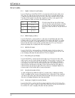
E2.3


Membrane Keypad Failure

As part of the OLSTs, a routine tests if any of the switches on the membrane keypad 

are shorted. If this occurs, this error is displayed. Replace the membrane keypad. If the 

problem persists, replace the microcontroller.

E2.4  Variable Redundancy Error

As part of the OLSTs, a routine tests the redundantly stored variables. All of the critical 

variables and data are stored in three places in RAM. If these three are not equal, this 

error is displayed. Replace the microcontroller.

E2.5  Variable Range Error

As part of the OLSTs, a routine tests each variable (actual RH, set RH, etc.) for valid 

values. If any variable has an invalid value, this error is displayed. To check the 

humidity sensor, attach a voltmeter to the two-pin header, H1, on the board; positive 

to pin 1 and negative to pin 2. Turn the unit on in room ambient humidity and check 

that the voltmeter reads between 1.0 and 3.5v. If it falls outside this range, replace the 

sensor. If it is inside this range, replace the microcontroller.

Note: This code can appear when the sensor and calibration bottle are not stabalized. 

Wait 30 minutes for them to fully stabilize. 

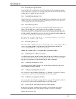
E3.1  Watchdog Time Out

The output of the watchdog circuit is an interrupt to the microcontroller. If the software 

is lost or the microcontroller is malfunctioning, the watchdog will interrupt the 

microcontroller. If this happens, this error is displayed.

Replace the microcontroller. If this problem persists, replace the board.

E4.1  Humidity Sensor Not Connected

On power up, a logic level on the humidity sensor connector is queried. If the sensor is 

not connected to the board, this error is displayed. Connect the sensor and verify the 

jumper is on the connector. If the problem persists, replace the board.

E4.2  Humidity Monitoring Circuit

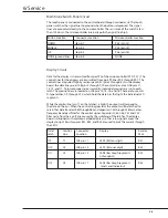
On power up, the ADC reads a resistor (JP3) on the board. If this value is invalid, this 

error is displayed. Replace the board.

E5.1  Calibration Voltage Error (2.5V)

As an on line test, the calibration voltage of 2.5V is measured. If this test fails, the ADC 

must be in error, and the error displayed. Replace the microcontroller.

E5.2  Calibration Voltage Error (0.0V)

As an on line test, the calibration voltage of 0.0V is measured. If this test fails, the ADC 

must be in error, and the error displayed. Replace the microcontroller.

E6.1  Thermal Fuse Opened (Heater Assembly Failure)

When heat is turned on, the heater current sense circuit shows the status of the 

thermostat and thermal fuse. If the thermal fuse opens, this error is displayed.

Replace the heater assembly.

Содержание Ohio Care Plus

Страница 1: ...Ohio CarePlus Servo controlled humidifier Operation Maintenance Service Manual and Installation Instructions Relative Humidity Enable Set RH Auto Shutoff Add Water System Fail 80 70 60 50 40...

Страница 2: ...ssary Ohmeda recommends that a telephone or written request for service advice be made to the nearest Ohmeda Regional Service Center This Product or any of its parts should not be repaired other than...

Страница 3: ...2 4 Using the Servo controlled Humidifier Basic operating procedure 4 1 5 Maintaining the Servo controlled Humidifier Maintenance schedule 5 1 Troubleshooting humidifier problems 5 2 Recording error...

Страница 4: ...play Brd Assy 8 3 Figure 8 4 Display Section Cntrl Display Brd Assy 8 4 Figure A 1 Humidity sensor installation A 3 Figure A 2 Rail installation A 4 Figure A 3 Humidity sensor cable attachment A 5 Fig...

Страница 5: ...0175 2311 000 to help ensure that static charges are safely conducted to ground and not through static sensitive devices Consult accompanying documents Indicates alternating current Indicates IEC Typ...

Страница 6: ...ion of this manual before put ting the unit into operation If the Servo controlled humidifier fails any portion of the checkout procedure it must be removed from use and repaired Do not use the Care P...

Страница 7: ...English it is the customer s responsibility to provide translation services Do not attempt to service the equipment unless this service manual has been consulted and is understood Failure to heed thi...

Страница 8: ...slu n ho person lu nebo pacient vlivem elektrick ho proudu respektive vlivem mechanick ch i jin ch rizik DA ADVARSEL Denne servicemanual findes kun p engelsk Hvis en kundes tekniker har brug for et an...

Страница 9: ...n s hk iskun mekaanisen vian tai muun vaaratilanteen vuoksi FR ATTENTION Ce manuel d installation et de maintenance est disponible uniquement en anglais Si le technicien d un client a besoin de ce man...

Страница 10: ...a vi skiptamanns a skaffa tungum la j nustu Reyni ekki a afgrei a t ki nema a essi j nustuhandb k hefur veri sko u og skilin Brot sinna essari a v run getur leitt til mei sla j nustuveitanda stj rnand...

Страница 11: ...reikalauja vadovo kita kalba ne angl suteikti vertimo paslaugas privalo klientas Nem ginkite atlikti rangos technin s prie i ros jei neperskait te ar nesupratote io eksploatavimo vadovo Jei nepaisysi...

Страница 12: ...ferimentos no t cnico operador ou paciente decorrentes de choques el tricos mec nicos ou outros PT PT ATEN O Este manual de assist ncia t cnica s se encontra dispon vel em ingl s Se qualquer outro se...

Страница 13: ...ch slu ieb je zodpovednos ou z kazn ka Nepok ajte sa o obsluhu zariadenia k m si nepre tate n vod na obluhu a neporozumiete mu Zanedbanie tohto upozornenia m e sp sobi zranenie poskytovate a slu ieb...

Страница 14: ...jo samo v angle kem jeziku e ponudnik storitve stranke potrebuje priro nik v drugem jeziku mora stranka zagotoviti prevod Ne posku ajte servisirati opreme e tega priro nika niste v celoti prebrali in...

Страница 15: ...nction to the Care Plus Incubator allows easyselection of humidity levels The Care Plus Servo controlled Humidifier augments the thermal efficiency of the Care Plus incubator to stabilize patient temp...

Страница 16: ...valve that releases that vapor into the incubator patient chamber The desired humidity level is entered on a control panel on the front of the humidifier The controller compares relative humidity read...

Страница 17: ...ed humidity level which appears in the display on the front of the humidifier can be adjusted using the humidity switches and M The controller compares the humidity display value to the control humidi...

Страница 18: ...hts when these switches are active If the indicator goes out you must push it again to use the humidity switches The power On Off switch is located on the left side of the humidifier controller next t...

Страница 19: ...trigger a Auto Shutoff Add water prompt The water level is low in the humidifier fill tray The prompt tone can be silenced by sliding out the fill tray but the indicator stays lit and the RH display...

Страница 20: ...2 General Information 2 4 2 4 Notes...

Страница 21: ...3 Examine the servo controlled humidifier for obvious signs of damage 4 Check that the humidifier controller is securely fastened to the incubator base 5 Locate the humidifier fill tray on the unders...

Страница 22: ...toff Add Water indicator goes out Operational checks 1 Make sure that the incubator is in the air control mode and that there is water in the humidifier fill tray 2 Check that the front door the porth...

Страница 23: ...operation of the Care Plus incubator refer to the incubator s Operation and Maintenance manual The servo controlled Humidifier fill tray holds enough water to last for approximately 10 hours Overfill...

Страница 24: ...4 Using the Servo controlled Humidifier 4 2 4 1 Notes...

Страница 25: ...ed in accordance with the procedures detailed in the Manual Service maintenance must be performed by a technically competent individual as described in the Repair Policy Operator maintenance This sche...

Страница 26: ...off System failure Electrical failure Note the readings on the RH display and set RH displays Discontinue use and call service E1 1 error code displayed Add Water has Fill humidifier tray with on powe...

Страница 27: ...olled Humidifier for cleaning If the humidifier has been exposed to body fluids check your hospital s infection control procedures You may need to wear protective clothing and eye glasses or to use sp...

Страница 28: ...ator parts Humidifier fill tray Disassemble the fill tray Clean the interior and seals with a mild detergent disinfectant solution such as Cavicide Rinse and thoroughly dry the parts before reassembly...

Страница 29: ...6 15 E1 3 RAM Test Failure 6 15 E1 4 Watchdog Circuit Failure 6 16 E2 1 Function Execution Error 6 16 E2 2 Anolog to Digital Converter Error 6 16 E2 3 Membrane Keypad Failure 6 16 E2 4 Variable Redund...

Страница 30: ...a Regional Service Office listed on the back cover Do not use malfunctioning equipment Make all necessary repairs or have the equip ment repaired by an Ohmeda Service Representative Parts listed in th...

Страница 31: ...source two priority level nested interrupt structure input output I O expansion and an on chip oscillator and clock circuits The I O ports on the microcontroller are listed below Port No Microcontrol...

Страница 32: ...requency This can be read from the ALE P line pin 30 on the microcontroller The capacitor C47 ensures that the microcontroller is held in reset until the voltage supply has stabilized The port designa...

Страница 33: ...e or 7FH Channel 3 is connected to the voltage divider of R44 and JP3 For the present design a 100K ohm resistor is installed in JP3 and the signal should be 2 5 volts If future sensor changes require...

Страница 34: ...t volume of the audio transducer The audio transducer is controlled by transistor Q3 Q3 is a darlington transistor which is used as a switch Resistor R7 set the base biasing current and resistor R8 is...

Страница 35: ...R9 of the AC line Resistors R64 and R9 limit the amount of current through U2 The other side of U2 pin 2 is connected to the junction of the thermal fuse and the thermostat Under normal conditions th...

Страница 36: ...17 To insure proper noise immunity individual grounds are run to each latch The ground lines are located on J2B pins 12 14 16 and 18 There are four octal D type latches U9 through U12 which hold the d...

Страница 37: ...data memory test by writing and reading various patterns to and from RAM If any location does not pass this test this error is displayed Replace the microcontroller if this error appears E1 4 Watchdo...

Страница 38: ...g Time Out The output of the watchdog circuit is an interrupt to the microcontroller If the software is lost or the microcontroller is malfunctioning the watchdog will interrupt the microcontroller If...

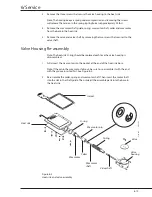
Страница 39: ...support are not service replaceable parts Order the entire heater valve and lid kit to replace these parts To replace the valve it is not necessary to disassemble the entire valve housing You only ne...

Страница 40: ...ing Re assembly Note The heat sink O ring should be replaced each time the valve housing is disassembled 1 Fully insert the wax motor into the pocket at the end of the heat sink bore Note If the pin i...

Страница 41: ...ming calibration and adjustment procedures or while working on the servo controlled humidifier with the power connected An electrical shock hazard does exist be certain to observe all safety precautio...

Страница 42: ...e 2 Slide the control board up out of the card guides 3 Disconnect the five connectors on the board 4 Remove the display board by removing the screw that secures it to the bezel 5 To re assemble rever...

Страница 43: ...cable out the rear of the base through the hole near the air filter and around the filter 11 Replace the filter Secure the filter cover with the filter mounting knobs The hole on the top of the filter...

Страница 44: ...on bottle was in a cold environment place the bottle in the incubator and allow it to warm before attaching it to the humidity probe If there is a large temperature difference between the solution in...

Страница 45: ...should come on 4 After five minutes pull out the fill tray and verify that the valve is open Allow the heater to cool before putting the humidifier back into service Note The Add Water prompt may come...

Страница 46: ...6 Service 6 18 6 18...

Страница 47: ...0077 400 4 Connector 6600 0430 600 5 Screw SHLDR PHN M3 5 6600 0524 400 6 O ring 0210 0559 300 7 Screw Fem 8 32 x 3 8 6600 0589 400 8 Connector mount kit includes magnets and holder 6600 0050 850 9 H...

Страница 48: ...housing beige 6600 0673 502 14 Label order when replacing item 13 6600 1858 100 15 Lock washer 1 4 int tooth 6600 0380 400 16 Ground label order when replacing item 13 0205 4737 300 17 Shaft retainer...

Страница 49: ...7 Illustrated Parts 7 3 7 3 Figure 7 2 Humidifier controller 8 7 6 8 5 9 10 11 12 13 15 4 3 1 2 22 21 19 20 16 18 17 14 CI 18 017 021 046 23...

Страница 50: ...ve 6600 0682 500 10 Valve housing 6600 0683 500 11 Screw 6 32 x 3 8 TRS PH SST 0140 6624 106 12 Guide 6600 0693 500 13 Small O ring 6600 0642 400 14 E clip 6600 0528 400 15 Wax motor spring 6600 0530...

Страница 51: ...tray rail assembly includes reed switch harness and connector 6600 0456 700 6 Cable clamp 0208 0335 300 7 Connector drawer plug 6600 0474 600 8 Screw 4 40 x 3 8 6700 0077 400 9 Screw 6 32 x 3 8 0142...

Страница 52: ...0 2 Shim holds temp probe in place 6600 0690 500 3 Foam gasket 6600 0852 500 4 Rear mounting block 6600 0688 500 5 Screw 8 x 1 00 self thd 6600 0083 400 Humidity sensor calibration kit 6600 0048 850 W...

Страница 53: ...8 Schematics 8 1 Figure 8 1 Wiring Diagram Servo controlled Humidifier 8 Schematics CI 18 059...

Страница 54: ...8 Schematics 8 2 Figure 8 2 Power Supply section of the Control Display Board Assembly CI 18 060...

Страница 55: ...8 Schematics 8 3 Figure 8 3 Digital section of the Control Display Board Assembly CI 18 061...

Страница 56: ...8 Schematics 8 4 Figure 8 4 Analog section of the Control Display Board Assembly CI 18 062...

Страница 57: ...8 Schematics 8 5 Figure 8 5 Heater Control section of the Control Display Board Assembly CI 18 063...

Страница 58: ...8 Schematics 8 6 Figure 8 6 Display section of the Control Display Board Assembly CI 18 064...

Страница 59: ...1 5 Amps Designed to UL544 and CSA 22 2 220 240 V 50 60 Hz models 230 V 15 0 75 Amps Designed to IEC 601 1 Power Consumption 150 Watts Fuses 2 0 Amps for 120V models time delay 1 0 Amp for 230V model...

Страница 60: ...to 1060 hPa Operating Relative Humidity Range 10 to 60 Transport and Storage Relative Humidity Range 0 to 95 Electromagnetic Compatibility EMC EC 801 2 Electrostatic Discharge Requirements Level 2 IE...

Страница 61: ...e the air filter cover on the back of the incubator by unscrewing the two cord wraps 5 Install the new humidifier sensor by feeding its cable from inside the hood through the sensor hole in the hood b...

Страница 62: ...ature sensor cable underneath the base platform Discard the old rails mounting screws and cable clip B The new rails use the same mounting holes as the old rails but new screws and spacers must be use...

Страница 63: ...14 Slide the two side rails all the way back into the pockets in the back rail and secure them in position by tightening the remaining four mounting screws Now fully tighten the two mounting screws th...

Страница 64: ...20 Insert the servo controlled humidifier fill tray and lid assembly 21 Re mount the incubator to the table top using the four mounting knobs removed earlier 22 Connect the humidifier power cord and s...

Страница 65: ...pear on the unit Symbol Description Consult accompanying documents Specifications The product is designed to meet a life span of 7 years However with proper maintenance and repairs the service life ca...

Страница 66: ...no warranty of merchantability or fitness for a particular purpose with respect to the product or parts thereof This Product is sold by Ohmeda under the warranties set forth in the following paragrap...

Страница 67: ......
Страница 68: ...A Tel 1 954 744 5600 GE Healthcare Shanghai GE China Hi tech Park No1 Huatuo Road Zhangjiang Hi tech Park Pudong Shanghai P R China 201203 GE 1 201203 Tel 8621 38777888 Fax 8621 38777402 Australia 130...

Отзывы: