6/Service
6-8 6-8
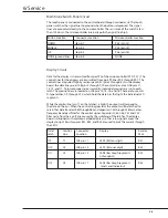
Membrane Switch Panel Circuit
The touch panel is connected to the control board through connector J6. The touch
panel switches the signal lines to ground when the button is depressed. The signal
lines are connected directly to the microcontroller. The resistance of the switch is less
than 100 ohms. The microcontroller internally pulls the signal line high.
Button Function
Connector Location
Microcontroller Location
DOWN
J6 pin 1
P3.4 (pin 14)
ENABLE
J6 pin 2
P3.5 (pin 15)
UP
J6 pin 3
P3.6 (pin 16)
NONE (ground line)
J6 pin 4
NONE
Display Circuit
Data for the displays is transmitted from port P2 of the microcontroller (P2.0-P2.7). The
control lines for the displays are transmitted from port P0 lines P0.4 through P0.7. The
control lines are pulled high by resistor pack R47 (pins 5 through 8). On the display
board, the data lines are at J2B pins 2 through 9; the control lines are at J2B pins 11,
13, 15, and 17. To insure proper noise immunity, individual grounds are run to each
latch. The ground lines are located on J2B pins 12, 14, 16, and 18. There are four octal
D-type latches, U9 through U12, which hold the data bits that light the individual LED
segments.
While the control line (pin 11 on the latches) is high, the outputs will respond to
the data on the bus. When the control line goes low, the outputs will be latched to
retain that data. Resistors R60 through R63 and capacitors C53 through C56 form a low
frequency band pass filter for the control signal. Capacitors C45, C46, C51 and C52
filter noise from the 5 volt line caused by the switching of the latches. The display
board is designed with common cathode displays so that a low signal causes the
display to light. Resistor packs R31, R32, and R33 are used to limit the current through
the LED’s.
Octal
Control
Connector
Display
Resistor
Latch
Line
Location
Pack
U9
C1
J2B pin 11
LED1 (RH tens digit)
R31
U10
C2
J2B pin 13
LED1 (RH ones digit)
R32
U11
C3
J2B pin 15
LED3 (Bar Graph segments
R33
A through H)
U12
C4
J2B pin 17
LED3 (Bar Graph segments
R33
I and J and Indicators)
Содержание Ohio Care Plus
Страница 20: ...2 General Information 2 4 2 4 Notes...
Страница 24: ...4 Using the Servo controlled Humidifier 4 2 4 1 Notes...
Страница 46: ...6 Service 6 18 6 18...
Страница 53: ...8 Schematics 8 1 Figure 8 1 Wiring Diagram Servo controlled Humidifier 8 Schematics CI 18 059...
Страница 54: ...8 Schematics 8 2 Figure 8 2 Power Supply section of the Control Display Board Assembly CI 18 060...
Страница 55: ...8 Schematics 8 3 Figure 8 3 Digital section of the Control Display Board Assembly CI 18 061...
Страница 56: ...8 Schematics 8 4 Figure 8 4 Analog section of the Control Display Board Assembly CI 18 062...
Страница 57: ...8 Schematics 8 5 Figure 8 5 Heater Control section of the Control Display Board Assembly CI 18 063...
Страница 58: ...8 Schematics 8 6 Figure 8 6 Display section of the Control Display Board Assembly CI 18 064...
Страница 67: ......


