2/General Information
2-3 2-3
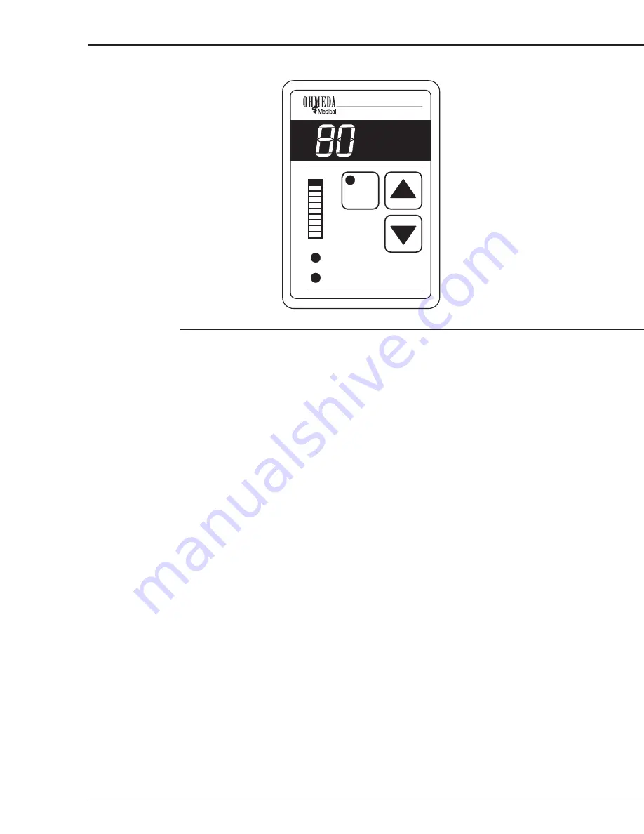
Figure 2-1
Control Panel
Operator prompts
Silencing a prompt
The system failure prompt cannot be silenced. The low water level prompt can be
silenced by sliding out the humidifier fill tray.
System fail
A system failure automatically shuts off the heater and triggers a continuous tone when
an electrical failure is detected. During a system failure, the system fail indicator lights
and a tone sounds. The following conditions trigger a system failure:
• A disconnected, open or short circuit in the humidifier sensor.
• An open circuit on the heater.
• A controller malfunction
Auto Shutoff/
Add Water
The Auto Shutoff/Add Water prompt automatically shuts off the heater. These
conditions trigger a Auto Shutoff/Add water prompt:
• The water level is low in the humidifier fill tray. The prompt tone can be silenced by
sliding out the fill tray, but the indicator stays lit and the RH display flashes. If there
is still no water in the tray when it is replaced, the prompt tone will start sounding
again within a few minutes.
• The humidifier fill tray is not fully inserted. Only the indicator will light; no tone will
sound. Power to the heater is disrupted until the tray is fully inserted.
Note: If the Auto Shutoff/Add Water prompt sounds and the fill tray is removed and
then replaced without water in it, there is a 30 second delay before the prompt sounds
again.
Note: This is not an instantaneous prompt. There will be a delay of no more than
20 minutes before the prompt sounds even when the fill tray is dry.
CI.18.014
%
Relative
Humidity
Enable
Set RH.
Auto Shutoff /
Add Water
System Fail
80%
70%
60%
50%
40%
Содержание Ohio Care Plus
Страница 20: ...2 General Information 2 4 2 4 Notes...
Страница 24: ...4 Using the Servo controlled Humidifier 4 2 4 1 Notes...
Страница 46: ...6 Service 6 18 6 18...
Страница 53: ...8 Schematics 8 1 Figure 8 1 Wiring Diagram Servo controlled Humidifier 8 Schematics CI 18 059...
Страница 54: ...8 Schematics 8 2 Figure 8 2 Power Supply section of the Control Display Board Assembly CI 18 060...
Страница 55: ...8 Schematics 8 3 Figure 8 3 Digital section of the Control Display Board Assembly CI 18 061...
Страница 56: ...8 Schematics 8 4 Figure 8 4 Analog section of the Control Display Board Assembly CI 18 062...
Страница 57: ...8 Schematics 8 5 Figure 8 5 Heater Control section of the Control Display Board Assembly CI 18 063...
Страница 58: ...8 Schematics 8 6 Figure 8 6 Display section of the Control Display Board Assembly CI 18 064...
Страница 67: ......


