6/Service
6-1 6-1
6/Service
In this section
Service Language Notice ..................................................................................................................................6-2
Repair Policy ..........................................................................................................................................................6-9
Functional Description ....................................................................................................................................6-10
Power Supply ..........................................................................................................................................6-10
Microcontroller .......................................................................................................................................6-11
Humidity Sensor ....................................................................................................................................6-11
Humidity Circuit .....................................................................................................................................6-11
Anolog-to-Digital Converter ..............................................................................................................6-11
Watchdog circuit ....................................................................................................................................6-12
Microswitch Circuit ...............................................................................................................................6-12
Safety Relay Circuit ................................................................................................................................6-12
Audio Prompt Circuit ............................................................................................................................6-13
Solid State Relay Circuit .......................................................................................................................6-13
Heater Current Sense Circuit .............................................................................................................6-13
Add Water Circuit ...................................................................................................................................6-13
Membrane Switch Panel Circuit .......................................................................................................6-14
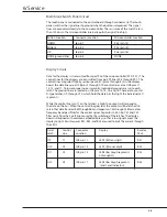
Display Circuit .........................................................................................................................................6-14
Error Codes ..........................................................................................................................................................6-15
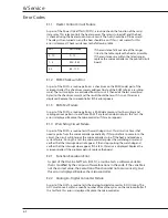
E1.1 Heater Control Circuit Failure ...................................................................................................6-15
E1.2 ROM Checksum Error ..................................................................................................................6-15
E1.3 RAM Test Failure ...........................................................................................................................6-15
E1.4 Watchdog Circuit Failure ............................................................................................................6-16
E2.1 Function Execution Error ...........................................................................................................6-16
E2.2 Anolog-to-Digital Converter Error..........................................................................................6-16
E2.3 Membrane Keypad Failure ........................................................................................................6-16
E2.4 Variable Redundancy Error .......................................................................................................6-16
E2.5 Variable Range Error ....................................................................................................................6-16
E3.1 Watchdog Time Out .....................................................................................................................6-16
E4.1 Humidity Sensor Not Connected............................................................................................6-16
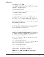
E4.2 Humidity Monitoring Circuit ....................................................................................................6-17
E5.1 Calibration Voltage Error (2.5V) ...............................................................................................6-17
E5.2 Calibration Voltage Error (0.0V) ...............................................................................................6-17
E6.1 Thermal Fuse Opened (Heat Assy Fail) ..................................................................................6-17
Repair Procedures .............................................................................................................................................6-17
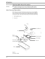
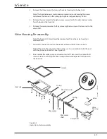
Lid disassembly & re-assembly .........................................................................................................6-17
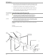
Humidifier controller disassembly/assembly ..............................................................................6-18
Humidifier control/display board removal/installation ...........................................................6-20
Humidity Sensor replacement ..........................................................................................................6-21
Sensor calibration .............................................................................................................................................6-23
Valve Checkout Procedure .............................................................................................................................6-24
Electrical Safety Check .....................................................................................................................................6-24
Содержание Ohio Care Plus
Страница 20: ...2 General Information 2 4 2 4 Notes...
Страница 24: ...4 Using the Servo controlled Humidifier 4 2 4 1 Notes...
Страница 46: ...6 Service 6 18 6 18...
Страница 53: ...8 Schematics 8 1 Figure 8 1 Wiring Diagram Servo controlled Humidifier 8 Schematics CI 18 059...
Страница 54: ...8 Schematics 8 2 Figure 8 2 Power Supply section of the Control Display Board Assembly CI 18 060...
Страница 55: ...8 Schematics 8 3 Figure 8 3 Digital section of the Control Display Board Assembly CI 18 061...
Страница 56: ...8 Schematics 8 4 Figure 8 4 Analog section of the Control Display Board Assembly CI 18 062...
Страница 57: ...8 Schematics 8 5 Figure 8 5 Heater Control section of the Control Display Board Assembly CI 18 063...
Страница 58: ...8 Schematics 8 6 Figure 8 6 Display section of the Control Display Board Assembly CI 18 064...
Страница 67: ......


