5/Maintaining the Servo-controlled Humidifier
5-4 5-4
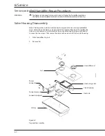
Figure 5-1
Disassembling the humidifier
Cleaning and disinfecting the Servo-controlled Humidifier
WARNING
Clean the humidifier after each patient.
CAUTION
w
Do not clean the humidifier with peroxide solutions, organic solvents, scouring
compounds, strong acids, or strong bases. These compounds may damage the
humidifier.
w
Do not autoclave or gas sterilize the humidifier lid assembly.
Divide the components according to cleaning methods. Using methods other than
those described in this section may damage the humidifier. See the Care Plus Incubator
O&M manual for proper cleaning of other incubator parts.
Humidifier fill tray
Disassemble the fill tray. Clean the interior and seals with a mild detergent-disinfectant
solution, such as Cavicide™. Rinse and thoroughly dry the parts before reassembly.
The fill tray may be autoclaved at 121°C.
Humidifier controller and lid components
Wipe the fill tray lid, front panel and sides of the controller with a cloth dampened with
mild detergent solution. Do not apply cleaning solutions on or near the power cord
connectors. Do not spray on cleaning solution or permit solutions to contact any
electrical parts.
Humidity Sensor
Wipe the humidity sensor with a cloth dampened with a mild detergent-disinfectant
solution, such as Cavicide™. Be sure to allow the sensor to thoroughly dry before
putting the Servo-controlled Humidifier back into operation.
Seals
Humidifier lid
Humidifier fill tray
CI.18.022
Содержание Ohio Care Plus
Страница 20: ...2 General Information 2 4 2 4 Notes...
Страница 24: ...4 Using the Servo controlled Humidifier 4 2 4 1 Notes...
Страница 46: ...6 Service 6 18 6 18...
Страница 53: ...8 Schematics 8 1 Figure 8 1 Wiring Diagram Servo controlled Humidifier 8 Schematics CI 18 059...
Страница 54: ...8 Schematics 8 2 Figure 8 2 Power Supply section of the Control Display Board Assembly CI 18 060...
Страница 55: ...8 Schematics 8 3 Figure 8 3 Digital section of the Control Display Board Assembly CI 18 061...
Страница 56: ...8 Schematics 8 4 Figure 8 4 Analog section of the Control Display Board Assembly CI 18 062...
Страница 57: ...8 Schematics 8 5 Figure 8 5 Heater Control section of the Control Display Board Assembly CI 18 063...
Страница 58: ...8 Schematics 8 6 Figure 8 6 Display section of the Control Display Board Assembly CI 18 064...
Страница 67: ......


