6/Service
6-5 6-5
The op-amp U3B is used to adjust the circuit for offset. This is the sensor (and circuit)
calibration. The potentiometer R30, one half of the voltage divider (R30/R20+R30), is
adjusted to calibrate the unit. The adjustability of this divider circuit is 0V to 4.85V.
The op-amp U3C is used to add 650mV to the sensor signal. The op-amp U3D is
configured as a differential amplifier combining the previous three op-amp outputs in
the following equation.
U3D = U3A + U3C - U3B
This resulting signal is read by the A/D converter.
Analog-to-Digital Converter
There are six A/D channels located on the microcontroller. The A/D converter requires a
reference voltage (VREF+ line, pin 1). This line is connected to the 5V net. The sensor, the
voltage dividers, and the A/D are all referenced to the same voltage; thus, there can be
no errors due to reference voltage variations. The A/D VREF- line is connected to the
ground plane, which provides immunity from variations on the ground plane.
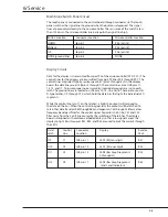
Channel 0 of the A/D is the sensor voltage. Channel 1 is the signal from the heater
current sense circuit. Channel 2 is the result of the divider R27 and R28. This line is
used to monitor the A/D functionality. Since this signal is one half of the 5V line (which
references the A/D), the resulting digital value from the A/D should be one half of full
scale, or 7FH. Channel 3 is connected to the voltage divider of R44 and JP3.
For the present design a 100K ohm resistor is installed in JP3 and the signal should
be 2.5 volts. If future sensor changes require a different software algorithm, a
different resistor will be installed in JP3. The resulting change in voltage will allow the
microcontroller to sense what type of sensor is installed. Channel 4 and 5 are not used
and are grounded.
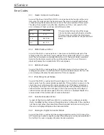
Watchdog Circuit
The IC labelled U5 is a retriggerable monostable multivibrator. The RC network of C40
and R21 defines the output pulse width. The output pulse width is set to approximately
1.6 seconds. The microprocessor outputs a pulse from P0.1 (pin 38), which is sensed
by pin 1 of U5. As long as the pulses occur at a time interval less than 1.6 seconds,
the output of the multivibrator (pin 13 of U5) stays at a high logic level. This output is
connected to the interrupt line of the microcontroller (INT0, pin 12), one input of U7A
(pin 1) and one input of U7D (pin 13). The microcontroller monitors the watchdog
through the INT0 line. This watchdog circuit turns off the heater through U7A and turns
on the audio alarm through U7D when its output results in a low logic level.
Microswitch Circuit
To insure proper fill tray engagement, a microswitch is installed on the back rail
assembly. This microswitch, actually two switches in series, is connected across pins
J5 pins 3 and 4. J5 pin 4 is connected to ground, while J5 pin 3 is connected to the
microswitch sense input line (pin 10 of the microcontroller).
Содержание Ohio Care Plus
Страница 20: ...2 General Information 2 4 2 4 Notes...
Страница 24: ...4 Using the Servo controlled Humidifier 4 2 4 1 Notes...
Страница 46: ...6 Service 6 18 6 18...
Страница 53: ...8 Schematics 8 1 Figure 8 1 Wiring Diagram Servo controlled Humidifier 8 Schematics CI 18 059...
Страница 54: ...8 Schematics 8 2 Figure 8 2 Power Supply section of the Control Display Board Assembly CI 18 060...
Страница 55: ...8 Schematics 8 3 Figure 8 3 Digital section of the Control Display Board Assembly CI 18 061...
Страница 56: ...8 Schematics 8 4 Figure 8 4 Analog section of the Control Display Board Assembly CI 18 062...
Страница 57: ...8 Schematics 8 5 Figure 8 5 Heater Control section of the Control Display Board Assembly CI 18 063...
Страница 58: ...8 Schematics 8 6 Figure 8 6 Display section of the Control Display Board Assembly CI 18 064...
Страница 67: ......


