background image

1

READ AND SAVE THESE INSTRUCTIONS

TRUE TOUCHSCREEN CONTROLLED ELECTRODE STEAM HUMIDIFIER

DESIGN SERIES “H”

INSTALLATION, OPERATION

AND MAINTENANCE MANUAL
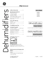
Ground Lug

On-Off-Drain
Switch

Drain Pipe

Circuit 
Breaker
(Optional)

Drain Valve

Circuit 
Board 

(Behind Door)

Voltage 
Transformer

Cylinder

Contactor

True
Touchscreen

Door Lock

Photo A

(Model HTGH Shown)

FORM ASX-16834-I

ISSUED: 08-16

Distributor 
Block

Door 
Interlock 
Switch

Current 
Transformers

Blue
Fill LED

Red
Drain LED

Orange High 
Water LED

ASX “H” SERIES HUMIDIFIER

Air Specialties Express, 448 S. Main St., P. O. Box 930040, Verona, WI 53593-0040    Phone: (877)945-9175    Fax: (608)845-6504    www.airspecialties.com

Summary of Contents for SERIES "H"

Page 1: ...in Valve Circuit Board Behind Door Voltage Transformer Cylinder Contactor True Touchscreen Door Lock Photo A Model HTGH Shown FORM ASX 16834 I ISSUED 08 16 Distributor Block Door Interlock Switch Current Transformers Blue Fill LED Red Drain LED Orange High Water LED ASX H SERIES HUMIDIFIER Air Specialties Express 448 S Main St P O Box 930040 Verona WI 53593 0040 Phone 877 945 9175 Fax 608 845 6504...

Page 2: ... Humidifier Startup Checklist 29 Humidifier Startup and Operations 30 Fan Distribution Units 31 32 Distribution Pipes 33 Short Absorption Manifold 34 35 Troubleshooting Symptom Cause and Action 36 41 Humidifier Operational Specifications 42 Humidifier Maintenance Checklist 43 Preventative Maintenance 44 Extended Shutdown Starting After Extended Shutdown 45 Replacement Cylinder 46 Removing the Cyli...

Page 3: ... Even discharged condensate water can be extremely hot Contact with these surfaces water or steam can cause personal injury To avoid severe burns always proceed with extreme caution Before any service or maintenance is performed turn off unit disconnect electrical service and allow humidifier unit to cool down completely WARNING De energize Electrical Supply Before any service or maintenance is pe...

Page 4: ...4 HSHH HTGH HSAH HSDH HRAB ...

Page 5: ... humidifier Fused Disconnect or Circuit Breaker By Others Air Flow Switch Air Flow Humidifier Cabinet Drain Line Air Gap Drain Fitting WARNING THE HUMIDIFIER CABINET CONTAINS HIGH VOLTAGE WIRING AND HOT SURFACES THE CABINET DOOR INCLUDES A LOCK AND ACCESS MUST BE LIMITED TO TRAINED AND QUALIFIED PERSONNEL ONLY THE DOOR MUST BE LOCKED AND KEY MUST BE KEPT IN A SECURE LOCATION AWAY FROM THE HUMIDIFI...

Page 6: ...er is boiled into steam it creates a scale build up that is left behind in the cylinder These substances left behind continue to change the properties of the supply water Having corrosive supply water can decrease the service life of the humidifier and the cylinder Also using excessively hard supply water can increase maintenance requirements It s recommended using a water supply that has a total ...

Page 7: ...th of steam hose that may be installed as shown in Figure B B 1 is 12 feet For a steam hose length over 12 feet refer to Figure D A drain T must be used to remove condensation that occurs in steam hose lengths over 12 feet It is preferable to have the steam hose rise vertically from the cabinet and then slope downward to the distributor pipe as shown If sufficient headroom is not available it is p...

Page 8: ...butor pipe Always avoid locating the distribution pipe upstream from any insulation in the duct as excess moisture may cause damage The distributor pipe may be located below the humidifier if the installation is made in accordance with Figure H A trap may be necessary to prevent steam from flowing back through the condensate return line In a vertical duct with either upward or downward air flow th...

Page 9: ...tances will be approximately 4 to 5 feet 4 If distance recommended is not possible then a drain pan may be required 5 If the air in the duct cannot accommodate the steam output the only recourse may be to lower the maximum output of the unit 6 If shorter absorption distances are required 3 feet or less multiple distributor pipes could be used Two pipes split off one steam hose or two pipes from a ...

Page 10: ...C65 cylinders and single phase humidifiers not using AX cylinders ELECTRICAL CONNECTIONS POWER MUST BE OFF BEFORE MAKING ANY ELECTRICAL CONNECTIONS Check unit electrical characteristics on the label on the outside of the cabinet The power provided must be the same as what is described on the label If it does not contact your Carnes Representative All local and national codes must be followed when ...

Page 11: ...25 1 25 Amp B600 16 6 H_DHMU 20 460 1 6 9 15 0 25 1 25 Amp B700 15 H_DHNU 20 575 1 6 9 12 0 20 1 15 Amp B700 12 H_DHCU 20 208 3 6 9 19 1 30 1 25 Amp B500 19 1 H_DHEU 20 230 3 6 9 17 3 30 1 25 Amp B500 17 3 H_DHTU 20 380 3 6 9 10 4 20 1 20 Amp B600 10 4 H_DHWU 20 415 3 6 9 9 6 20 1 20 Amp B600 9 6 H_DHGU 20 460 3 6 9 8 6 15 1 15 Amp B700 8 6 H_DHHU 20 575 3 6 9 6 9 15 1 15 Amp B700 6 9 H_DHCU 30 20...

Page 12: ... 47 9 80 2 40 Amp C12 24 H_GHGU 100 460 3 34 4 43 3 70 1 60 Amp C12 21 7 H_GHHU 100 575 3 34 4 34 6 60 1 50 Amp C12 17 3 HSHH HTHH H_HHCU 125 208 3 43 119 5 200 4 40 Amp C62 2 29 8 H_HHEU 125 230 3 43 108 175 4 40 Amp C62 2 27 H_HHTU 125 380 3 43 65 3 100 2 50 Amp C12 2 16 3 H_HHWU 125 415 3 43 59 8 90 2 45 Amp C12 2 15 H_HHGU 125 460 3 43 54 0 90 2 40 Amp C12 2 13 5 H_HHHU 125 575 3 43 43 2 70 2 ...

Page 13: ...ontactor 9 High Water Sensor behind cylinder 10 Fill Cup 11 Fill Valve not shown 12 Steam Hose 13 Electrode Connector 14 LCD True Touchscreen 15 Circuit Breakers Option 16 Cylinder 17 Cylinder Fitting 18 Drain Valve 19 Lock 20 Water Inlet Hose 21 Water Inlet Fitting 22 Fill Valve Inlet Push On Connector not shown 23 Cooling Fan 1 2 3 4 5 6 7 8 10 12 13 1 14 3 15 16 17 18 19 20 21 23 ...

Page 14: ...r the control circuit No outside power supply is required for the control circuit 2 If an air flow switch or high limit humidistat is not used jumpers must be installed before the humidifier will operate Controls should be connected to the terminals on the circuit board as shown in Figure L using 18 AWG wire Avoid running control wiring near high voltage wires NOTES 1 Observe proper polarity when ...

Page 15: ...ir flow If the steam distributor pipe is located in a duct where there is no air flow and the control humidistat is calling for humidity steam would be discharged into the duct where it would immediately condense Air flow may be detected by several methods The humidistat circuit may be interlocked by using a fan relay if the fan is direct driven A fan relay is not recommended if a belt driven fan ...

Page 16: ...10 90 RH Differential is 5 non adjustable RED N C BROWN N O To Terminal 2 or 4 ORANGE COMMON To Terminal 2 or 4 N C Red is switched to common Orange during RH Rise N O Brown is switched to common Orange during RH Drop NOTE The HXHAA has 6 152mm leads and a green grounding wire for use with non conducting conduit WALL HUMIDISTAT ON OFF CONTROL Model HXHAM Model HXHAA The Model HXHAM is a wall mount...

Page 17: ...STAT PROPORTIONAL CONTROL The Model HXHAN is an intelligent humidistat solution used exclusively for duct mounted installations The humidistat is capable of providing both humidity and temperature measurements from inside the duct The microprocessor control takes the temperature into consideration when calculating the humidity to provide an extra degree of precision Snap on plastic cover Aluminum ...

Page 18: ...closed common ground contact of the switch is switched to normally closed contact Avoid locations where excessive moisture corrosive fumes or vibrations are present Setpoint Factory Set 0 07 1 8mm w g Field Adjustable 0 07 to1 1 8 to 25 4mm w g Sensing Element Neoprene diaphragm Adjustment Note Units are shipped at minimum setpoint To increase setpoint turn adjustment screw clockwise Adjustable 0 ...

Page 19: ...l humidistat and high limit humidistat are output on pin1 of J16 and J17 respectively 18VDC is set as the supply default but the switches on designators SW5 can be flipped to the left to alternatively supply 24VAC as seen in Photo G for the H690 0107 circuit board blue The humidistat and high limit can be changed independently The switch labeled Hu is switched for humidistat voltage output and the...

Page 20: ...creen makes setting up CarnesLink easy and convenient See the CarnesLink Communication Protocol Installaion Operation and Maintenance Manual for further info NETWORKING If multiple units are required due to high capacity demand over 200 lb per hour single unit networking can be done Units can be interconnected with parallel signal wiring This setup is usually done to facilitate running multiple un...

Page 21: ...res four navigation buttons Carnes Logo providing contact info to the factory and the company website Steam Menu Menu and Settings The Home Screen will display a Service Required indicator when a current service issue is indicated The Service Required and Steam Output number will illuminate red Tap on Service Required to access the service required page which indicates what service issue is being ...

Page 22: ...Drain Valve allows water to drain from the humidifier An analogous indicator and a description of its operation is offered in the Menu screen under Component Activity HIGH WATER LED The HIGH WATER LED is an orange light illuminated when the High Water Sensor is activated An activated High Water Sensor indicates that the water has risen to the maximum allowable level in the cylinder This can be a n...

Page 23: ...same way only Control Humidistats are wired to port J16 of the circuit board and High Limit Humidistats are wired to port J17 Both ports have the same number of pins and connection layout When using an on off humidistat the percentage should be either 100 or below 20 In this case the control is either calling for full output or no output On Off humidistats are dry contact switches They will have t...

Page 24: ...r the touchscreen controller on the circuit board is properly communicating with the microcontroller and that the microcontroller is properly communicating with the data communication chip if present The Communication indicator is a green when the LCD display is communicating properly with the control board If there is a red X the touchscreen has likely lost communication with the control board an...

Page 25: ...e nominal output The nominal output of the unit is listed on the nameplate and the Electrical Data help page This page consists of a counter where the user can monitor the life in hours of the cylinder When changing a cylinder press the Reset button on this page to reset the timer The Cylinder Life Counter only counts the amount of actual runtime of the cylinder the time when the contactor is pull...

Page 26: ...the humidifier will continue to run If the humidifier cannot reach normal max controlled Setpoint the humidifier will shut down after the High Water Timeout value elapses This page is where the Boil Down Timer is set The Boil Down Timer is variable between 0 and 255 seconds with a default value of 25 seconds Setting the Boil Down Timer higher will result in an increased water level and less condit...

Page 27: ...rain the cylinder completely after 72 hours of idle operation The LCD Auto Dim is disabled by default This option when enabled will automatically turn off the backlight of the LCD after 15 minutes of idleness This feature can save on energy consumed The Steam Output Units is disabled or set to Lb by default This option when set to Kg will turn the steam readout on home page into Kg Hr instead of L...

Page 28: ...nection at fill yes no Water pressure 20 120 psi yes no Water supply shutoff within 6 ft yes no PVC yes no Copper yes no DRAIN LINE Connection pipe fitting to trap yes no Slope to drain yes no CYLINDER Properly installed and secured yes no Water pressure 20 120 psi yes no Wire connectors pushed completely down on electrode rods yes no WIRING No lose wiring connections and connectors yes no CONTROL...

Page 29: ...AD yes no The humidifier will undergo a self diagnostic when the power is turned on activating the LED s and other internal components If the above listed prerequisites are fulfilled the humidifier will start filling the cylinder and begin normal operation Started by ________________________________________ Date of Startup ___________________ Company ________________________________________ Unit S...

Page 30: ...nder and fresh water the fill and drain solenoid valve may cycle for brief periods until the water has come to a complete boil 11 In areas with low conductivity water full output may not be reached until the humidifier has conditioned the water by repeated cycles of filling boiling and refilling The length of this process will vary but may require several hours up to a day under certain conditions...

Page 31: ...made from the circuit board to the 12 Pin fan connection Green This connection is already assembled in the factory Photo I Fans Steam Hose Fan distribution units must be mounted securely on a level and plumb surface at least three feet below the ceiling for a Model HXBHB and at least four feet below the ceiling for a Model HXBHC to prevent steam condensing on the ceiling surface Allow 20 feet in f...

Page 32: ...of the humidifier connector should be routed to pin 1 of the fan distribution unit connector Pin 2 should be routed to pin 2 etc Use a small regular head screwdriver to connect each conductor into the male connector It is important to make sure the conductor is grasped inside the screw compression and not the wire insulation A remote fan distribution unit should not be mounted any more than 40 fee...

Page 33: ...311mm 94 2388mm 7 8 HXPBB100S 95 2413mm 98 2489mm 7 8 HXPBB104S 99 2515mm 102 2591mm 7 8 HXPBB108S 103 2616mm 106 2692mm 7 8 HXPBB112S 107 2718mm 110 2794mm 7 8 HXPBB116S 111 2819mm 114 2896mm 7 8 HXPBB120S 115 2921mm 118 2997mm 7 8 See Note A NOTE A The mounting plate on these pipes is adjustable to compensate for slight variations in ductwork dimensions The N dimension is shown at both maximum a...

Page 34: ...ed for absorption is dependent on a number of factors some of which are air velocity steam volume air temperature and characteristics of air flow in the duct For minimum absorption distance the manifold should be located in the warmest air stream of the duct and where fully developed laminar air flow occurs Table 5 Duct Height Tubes 012 3 014 016 4 018 5 020 022 6 024 7 026 028 8 030 9 032 034 10 ...

Page 35: ...ope with a minimum rise of 2 for every 12 of run The steam manifold may be located below the humidifier if the installation is made in accordance with Figure T The steam manifold cannot be installed in a vertical duct The manifold has an integral mounting flange for ease of installation Separate mounting flanges supplied by others are needed to mate with the manifold Refer to Figure U If the steam...

Page 36: ...idifier drains continuously Piece of mineral is partially blocking drain so it will not close properly Cycle drain If it does not clear clean as necessary Drain plunger is worn out preventing drain valve from closing completely Repair or replace as necessary Water in duct or spitting from distributor pipe Steam hose and condensate return hose do not have a continuous slope Condensate accumulates a...

Page 37: ...stem static pressure Supply air system must be evaluated if static pressure is too high Locate and correct issue Back pressure in steam hose is too high Check for the following too long of steam line runs sags dips horizontal runs not allowing for proper condensate removal improper sloping of steam lines and condensate line Foaming Remove impurities inside the cylinder If cleaning of cylinder was ...

Page 38: ...tool and pulling the strainer out If 24VAC is present and strainer is clean the fill valve may be defective If the High Water Sensor is activated the fill valve will not be allowed to open In this case the blue LED on the front panel will be off Make sure the drain solenoid is not partially open due to blockage restriction or malfunction Drains continuously The most common cause is to have a piece...

Page 39: ...f less than 12 from the distributor pipe to the top of the humidifier cabinet it may be better to route the drain below the unit rather than connecting at the top of the cabinet If the condensate return line is connected to the fitting at the top of the humidifier cabinet make sure that traps have not been installed in the return line A trap is only needed if the return line is routed to a separat...

Page 40: ...ch in turn causes low water levels Low water levels cause arcing Drain lines should be inspected when cylinders are changed and thoroughly cleaned if necessary A defective drain solenoid valve will prevent proper draining The solenoid should be checked to verify that it moves freely when 24VDC is applied to the coil When placed in the Drain position both the drain and fill valves open and it is ve...

Page 41: ... cause over concentration and malfunction due to foaming These are just some examples of what can go wrong if the fill and drain rates are not controlled and maintained TROUBLE SHOOTING SYMPTOM CAUSE AND ACTION Continued SYMPTOM CAUSE ACTION Foaming Foaming is usually due to foreign matter or impurities getting into the cylinder through normal water supply Detergents cleaning agents used to clean ...

Page 42: ...by their own control signal 22 Automatic Drain of cylinder water will take place when there is a demand signal loss for 72 hour drain setting is turned on Unit will remain in stand by in the event that a quick startup is required 1 Provide self contained electronically controlled steam generating humidifiers of the size s shown on plans as manufactured by Carnes Company Verona WI 2 Carnes Humidifi...

Page 43: ...valve installed ground wire attached yes no New cylinder installed and hose clamps tightened yes no New cylinder model _____________________________ Should be same as removed cylinder Cylinder plug numbers match cylinder numbers yes no Cylinder plugs snug and in good condition yes no Electrical wiring not loose and in good condition yes no Steam and condensate hoses in good condition no kinks in h...

Page 44: ...tness 3 Humidifier unit inspect internal hoses for sediment build up or degradation Clean or replace as necessary Also check tightness of hose clamps Tighten as necessary 4 Inspect fill valve strainer Industrial commercial unit fill valve strainer is located at the connection point of the water inlet hose to valve Strainer is located inside the valve at the threads Pop out using a non sharp tool a...

Page 45: ...e humidifier is completely drained of water 3 Turn the On Off rocker switch to the OFF position 4 Shut off the main external power to the humidifier unit 5 Turn the supply water off at the shut off valve STARTING AFTER EXTENDED SHUTDOWN 1 Inspect the humidifier for any damage Check to make sure the mounting and installation has not been altered 2 Turn on the main external power to the humidifier u...

Page 46: ... or 9 digit model number from the cylinder label You will also need to provide the humidifier model number and serial number located on the sticker on the front of the unit CARNES RECOMMENDS THAT THE CYLINDER REMAIN EMPTY DURING EXTENDED SHUTDOWN PERIODS THIS WILL PREVENT THE POSSIBILITY OF CORROSION OF THE ELECTRODES AND THE ACCUMULATION OF ALGAE AND BACTERIA GROWING IN THE CYLINDER NOTE Steam Ou...

Page 47: ...power Off at the external shut off 5 Remove all terminal plugs from the cylinder 6 Loosen the steam hose clamp and remove the steam hose from the cylinder 7 Using a flat head screwdriver Remove the cylinder strap keeping the cylinder in place 8 A and B sized cylinders are threaded Unscrew the cylinder counter clockwise and lift up and out 9 C sized cylinders are seated into the brass plumbing with...

Page 48: ...cylinder with the white cylinder straps not labeled 5 Do not over tighten as this may damage the cylinder 6 Connect the terminal wires to the electrodes so that the numbers match those on the cylinder Push the plugs onto the pins to ensure the electrode plugs are firmly in place 7 Place the steam hose onto the steam outlet and tighten the steam hose clamp 8 Turn main power On at the external shut ...

Page 49: ...m We will have your agent contact you Thank you for choosing Carnes Humidifiers Requested information is located on a label on the outside of the humidifier cabinet on the lower left corner MODEL LBS HR SERIAL NO CODE POWER SUPPLY VAC HZ PH AMPS Part Cylinder Humidifier Specifications Quantity HXCBAX145 AX Contact Carnes Rep for more info HXCBAX220 AX 005 010 lb hr 120V 1 Ph HXCBAX380 AX 005 010 l...

Page 50: ...50 2 6 7 9 10 21 18 17 24 14 12 11 SEE TABLE 2 FOR STEAM CYLINDER SELECTION TYPE AX TYPE B TYPE C 29 1 3 4 22 25 23 REPLACEMENT PARTS 28 13 1 ...

Page 51: ...EMBLY Single Cylinder H_AH H_DH H_GH H 690 1671 11 WATER FILL TUBE SUB ASSEMBLY Dual Cylinder H_HH H 690 1672 12 CLEAR HOSE 5 8 ID ALL HXLA 13 PLASTIC ELBOW 5 8 HOSE TO 5 8 HOSE ALL H 999 9690 14 DRAIN SOLENOID VALVE H_GH H 999 7448 14 DRAIN SOLENOID VALVE H_HH H 690 1091 R H 14 DRAIN SOLENOID VALVE H_AH H_DH H_HH H 690 1092 L H 17 AX CYLINDER FITTING H_AH H 998 5703 17 B CYLINDER FITTING H_DH H 9...

Page 52: ...999 7405 999 8035 H_DHH 20 3 575 B700 998 9539 999 7389 690 3019 999 7412 999 8035 H_DHC 30 3 208 B500 998 9537 999 7480 690 3019 999 7409 999 8035 H_DHE 30 3 230 B500 998 9537 999 7389 690 3019 999 7409 999 8035 H_DHT 30 3 380 B600 998 9535 999 7389 690 3019 999 7407 999 8035 H_DHW 30 3 415 B600 998 9535 999 7389 690 3019 999 7406 999 8035 H_DHG 30 3 460 B700 998 9537 999 7389 690 3019 999 7406 9...

Page 53: ...0 3 230 4150 C62 2 998 9538 999 7480 4 690 3046 999 7401 4 999 9524 H_HHT 150 3 380 3315 C12 2 998 9535 999 7480 2 690 3046 999 7402 2 999 8035 H_HHW 150 3 415 4315 C12 2 998 9535 999 7480 2 690 3046 999 7402 2 999 8035 H_HHG 150 3 480 6150 C12 2 998 9537 999 7480 2 690 3046 999 7402 2 999 8035 H_HHH 150 3 575 7150 C12 2 998 9539 999 7389 2 690 3019 999 7414 2 9998 8035 H_HHC 175 3 208 2175 C62 2 ...

Page 54: ...the warranty period and at Seller s option the return of such products to Seller f o b its factory when such return is feasible Seller reserves the right to satisfy its warranty obligation in full by reimbursing Buyer for all payments it makes hereunder and Buyer shall thereupon return the products to Seller Seller shall have the right to remedy such defects THEFOREGOINGWARRANTIESAREEXCLUSIVEANDIN...

Page 55: ...55 ...

Page 56: ...56 ...

Reviews: