


MPC8349E-mITX-GP Reference Design Platform User’s Guide, Rev. 0
Freescale Semiconductor
5
Preliminary—Subject to Change Without Notice
MPC8349E-mITX-GP Board
1.2.2
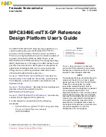
External Interrupts
Figure 3
shows the external interrupt circuitry to the MPC8349E.
Figure 3. MPC8349E Interrupt Circuitry
Following are descriptions of the interrupt signals shown in
Figure 3
:
•
PHY interrupt (GBE1_IRQ) and RTC interrupt (RTC_IRQ).The VSC8201 GBE PHY interrupt is
ORed with the DS1339 RTC interrupt and connected to IRQ2 of the MPC8349E. Therefore, the
system software can detect the status of the Ethernet link, the PHY internal status, and the RTC
status.
•
PCI interrupt (PCI_INTA, PCI_INTB). The 32-bit PCI slot INTA and INTB are connected to the
IRQ4 and IRQ5 of the MPC8349E, respectively.
•
USB over current (USB2_IRQ). The USB2 power supply has an over current detection circuit and
generate an interrupt when the current limit reaches (2A) or a thermal shutdown or under voltage
lockout (UVLO) condition occurs. This interrupt pin generates an interrupt to IRQ3 of the
MPC8349E.
GBE1_IRQ
RTC_IRQ
USB2_IRQ
PCI_INTA
PCI_INTB
IRQ2
IRQ3
IRQ4
IRQ5
IRQ6
MPC8349E
External Logic