


MPC8349E-mITX-GP Reference Design Platform User’s Guide, Rev. 0
14
Freescale Semiconductor
Preliminary—Subject to Change Without Notice
MPC8349E-mITX-GP Board
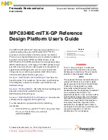
Ethernet port, USB port, parallel port, RS-232, and so on. A typical setup using a USB port emulator is
shown in
Figure 11
.
Figure 11. Connecting the MPC8349E-mITX-GP Board to A Parallel Emulator
The 16-pin generic header connector carries the COP/JTAG signals and the additional signals for system
debugging. The pinout of this connector is shown in
Figure 12
.
Figure 12. MPC8349E-mITX-GP Board COP Connector
PC
MPC8349E ITX
P17
USB
Emulator
TDI
Pull-up
TCK
TMS
SRESET
HRESET
CKSTP_OUT
GND
TRST
Pull-up
NC
GND
GND
NC
GND
1
TDO