


MPC8349E-mITX-GP Reference Design Platform User’s Guide, Rev. 0
Freescale Semiconductor
15
Preliminary—Subject to Change Without Notice
MPC8349E-mITX-GP Board
1.3
MPC8349E-mITX-GP Assembly
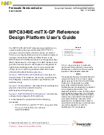
The MPC8349E-mITX-GP board PCB top view is shown in
Figure 13
, with the references of LEDs,
jumpers, headers, and switches.
Figure 13. MPC8349E-mITX-GP Top View
1.4
Connectors
This section describes the MPC8349E-mITX-GP connectors and their pin assignments.
1.4.1
Case Connector
The case connector (J10) connects to the case power switch, power LED, reset switch.
•
PWR_SW can connect to the 2-pin power push button on the front panel.
•
PWR_LED lights when the system is turned ON.
•
RST_SW can connect to the 2-pin reset push button on the front panel.
Pin 1
P15 RS-232-COM1
USB5
P1
BT1 Battery Holder
D8
P17
P18 ATX Power
U1
DIM
M
1
8
4
DDR1
ENET0 (top)
Reserved (bottom)
S5 PowerOn
J10
D1
J14
J9
S3
J19
32-bits PCI
COP Connector
P14
P11
J21
D9
D2
J22
ABCDEFGH