


MPC8349E-mITX-GP Reference Design Platform User’s Guide, Rev. 0
Freescale Semiconductor
13
Preliminary—Subject to Change Without Notice
MPC8349E-mITX-GP Board
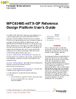
Figure 9
shows the connection of USB port 0 and port 1.
Figure 9. USB Port 0 and Port 1 Connections
1.2.11
PCI Subsystem
The MPC8349E has two PCI interfaces (PCI1 and PCI2). PCI1 interface is not used. PCI2 connects to a
32-bit 3.3 V PCI slot.
Figure 10. PCI Subsystem
1.2.12
COP/JTAG Port
The common on-chip processor (COP) is part of the MPC8349E JTAG module and is implemented as a
set of additional instructions and logic. This port can connect to a dedicated emulator for extensive system
debugging. Several third-party emulators in the market can connect to the host computer through the
Table 5. USB Port 0 and Port 1 Configurations
Port
Interface Type
USB PHY
Operating Mode
Connector Type
USB Port 1
ULPI
USB3300
DR Host/Device/OTG
1 x Type Mini-AB Receptacle
MPC8349E
Po
rt
1
DIR
USB3300
D[7:0]
STP
NXT
CLKOUT
CPEN
ULPI_D[7:0]
ULPI_STP
ULPI_NXT
ULPI_CLK
ULPI_DIR
MIC2505
VBUS
DM
DP
ID
USB Type Mini-AB
5 V
MPC8349E
32-Bit PCI2
PCI2-AD[0:31]
PCI2-CBE[0:3]
PCI2-REQ0
PCI2-GNT0
PCI2-CTRL
32-Bit 3.3 V
PCI Slot
PCI2-REQ0
PCI2-GNT0