


Accelerometer Demonstration
MC1322x SMAC Demonstration Application User’s Guide, Rev. 1.3
Freescale Semiconductor
4-3
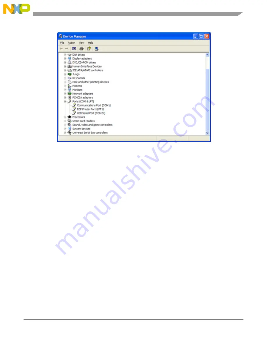
Figure 4-1. COM Port Determination in Device Manager
6. If the COM port chosen for
Freescale Zigbee/802.15.4 MAC COM Device
is not a port within Ports
1-10, then perform the following tasks:
a) Double click on
Freescale Zigbee/802.15.4 MAC COM Device
in the Device Manager window
and the Properties window will appear.
b) Select the Port Settings tab and then click the Advanced button.
c) Go to the Com Port Number drop down menu and select a COM port between 1-10 that is not
in use.
4.6
Verifying Operation
1. Check for the ping packet. The Accelerometer application sends a ping packet to the PC_Radio
every two (2) seconds as indicated by LED2. The Accelerometer Board quickly blinks LED2
indicating that the ping packet is sent. The PC_Radio receives the ping and toggles LED2 upon
reception. Once connectivity between the PC_Radio and the Accelerometer Board is verified, go
to
Step 2
.
2. To check if the Accelerometer Board is working, move the Accelerometer Board. LED1 blinks,
which indicates that the Accelerometer Board has detected movement.
3. With the default application, data that represents movement of the Accelerometer Board is sent to
the PC_Radio. When the PC_Radio receives this data, LED2 toggles.
4. Select the Raw Data applet from the Triax application. The Raw Data applet shows the X, Y, and
Z axes A/D values as reported by the Accelerometer Board. When the board is laying flat, the raw
values should read approximately 0g for both the X and Y axes. However, the Z axis should read
approximately 1g. As shown in
Figure 4-2
, when the Accelerometer Board is moved, the values of
the X, Y, and Z axes are updated on the Raw Data applet.