NXP Semiconductors MC13224V Скачать руководство пользователя страница 23

Wireless UART Demonstration

MC1322x SMAC Demonstration Application User’s Guide, Rev. 1.3 

Freescale Semiconductor

2-3


Figure 2-3. Release, Debug, and Settings

The 

WirelessUART.bin

 file is placed at the following directory location:

[Project Directory]\Release\Exe\

4. Load the 

WirelessUART

 application to the boards. Connect the JTAG interface to the board, then 

click the Debug button on the IAR Embedded Workbench IDE.

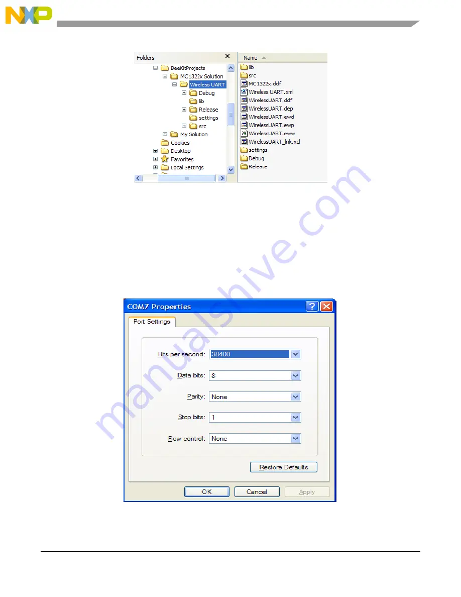
5. Use a PC terminal communications program, such as Hyper Terminal, and set the correct baud rate, 

data bits, parity, COM port, and flow control. 

Figure 2-4

 shows the default MC1322x SMAC 

RS-232 settings.

Figure 2-4. Default SMAC RS-232 Settings

Содержание MC13224V

Страница 1: ...Document Number 22xSMACDAUG Rev 1 3 09 2011 MC1322x Simple Media Access Controller Demonstration Applications User s Guide...

Страница 2: ...claims any and all liability including without limitation consequential or incidental damages Typical parameters that may be provided in Freescale Semiconductor data sheets and or specifications can a...

Страница 3: ...pen Compile and Execute the Wireless UART 2 2 Chapter 3 Connectivity Test 3 1 Loading the Connectivity Application 3 2 3 2 UART USB Virtual Com Port Setup 3 3 3 3 Starting the Connectivity Test 3 4 3...

Страница 4: ...Execute the Repeater 8 2 8 3 Repeater Menu Configuration and Settings 8 5 8 4 Running the Repeater Demonstration 8 7 8 4 1 Creating a Sniffer 8 7 8 4 2 Running a Dummy Repeater 8 7 Chapter 9 Weather S...

Страница 5: ...322x SMAC Demonstration Application User s Guide Rev 1 3 Freescale Semiconductor iii 10 5 1 Using the Serial Interface 10 9 10 5 2 Using The LCD Interface 10 11 10 6 Verifying the Transmitted Image 10...

Страница 6: ...MC1322x SMAC Demonstration Application User s Guide Rev 1 3 iv Freescale Semiconductor...

Страница 7: ...PI is similar to previous SMAC APIs For more detail about the APIs see the MC1322x Simple Media Access Controller SMAC Reference Manual 22xSMACRM Available Devices The MC1322x family is available as t...

Страница 8: ...des test mode continuous tx modulated unmodulated etc Packet Error Rate and Range LQI measurements Chapter 4 Accelerometer Test Provides an overview of the Accelerometer Demonstration application whic...

Страница 9: ...An example is the P E BDM Multilink debugger for HCS08 CBC Cipher Block Chaining CBC MAC Cipher Block Chaining Message Authentication Code CCM Counter with CBC MAC CTR Counter dBm Decibels referred t...

Страница 10: ...ace for up to 64 KB The S19 can be generated with CodeWarrior IDE and is the product from the linking process S19 does not contain additional information to a debugger where to look for source files S...

Страница 11: ...erate an SMAC demonstration application For more details on installing BeeKit and BeeKit operation see the BeeKit Wireless Connectivity Toolkit User s Guide BKWCTKUG This chapter also shows how to set...

Страница 12: ...ion User s Guide Rev 1 3 1 2 Freescale Semiconductor Figure 1 2 selecting SMAC Codebase In BeeKit a Codebase is a set of files and rules that permit users to generate the final applications This step...

Страница 13: ...ject as shown in Figure 1 3 Figure 1 3 Creating a new project If users create a new project and there is not a an existing solution then users are also creating a solution The solution must have a nam...

Страница 14: ...Word of the 128 bits to be used as initial counter on the ciphering engine Security Default COUNTER1 Second Significative 32 bit Word of the 128 bits to be used as initial counter on the ciphering eng...

Страница 15: ...cale Semiconductor 1 5 6 Users must now validate the solution as shown in Figure 1 5 The validation process helps users find possible inconsistencies between the selected hardware and properties Figur...

Страница 16: ...Embedded Workbench IDE This example uses the repeater application 1 As shown in Figure 1 7 open the My Solution eww file Figure 1 7 Opening a project 2 Make the project by clicking the Make button Fi...

Страница 17: ...utton Figure 1 11 Figure 1 11 Go 1 2 JTAG Debugging 1 To debug an application select Debug at the Work space window as shown in Figure 1 12 Figure 1 12 IAR Embedded Workbench Work Space Debug and Rele...

Страница 18: ...s Guide Rev 1 3 1 8 Freescale Semiconductor Figure 1 14 Debugger Setup 4 Ensure that the JTAG Debugger is connected to the PC and to the board 5 On the Project window press the CTRL D keys or just cl...

Страница 19: ...ram The two boards can be attached to two different serial ports of the same PC if needed but Freescale recommends using two PCs when possible 1 Connect each of the boards to a separate PC either with...

Страница 20: ...Double click on USB Serial Port in the Device Manager window The Properties window appears b Select the Port Settings tab and then click on the Advanced button c Go to the COM Port Number drop down me...

Страница 21: ...t Wireless Connectivity Toolkit User s Guide The MC1322x SMAC Wireless UART demonstration application is protocol compatible with previous SMAC Wireless UART applications those that run on the MC1319x...

Страница 22: ...t Wireless Connectivity Toolkit User s Guide BKWCTKUG 2 2 Open Compile and Execute the Wireless UART 1 Using the IAR Embedded Workbench open the Wireless UART work space Wireless UART eww as shown in...

Страница 23: ...ion Project Directory Release Exe 4 Load the WirelessUART application to the boards Connect the JTAG interface to the board then click the Debug button on the IAR Embedded Workbench IDE 5 Use a PC ter...

Страница 24: ...program set the properties in the optional settings as shown in Figure 2 5 Figure 2 5 Additional Terminal Program Settings 7 Start the serial communication software and send any characters using the k...

Страница 25: ...Terminal Session Board 2 also shown in Figure 2 7 Figure 2 7 Wireless UART Board 1 Sending and Board 2 Receiving This is a two way communication protocol where the boards will retry their packets up t...

Страница 26: ...Wireless UART Demonstration MC1322x SMAC Demonstration Application User s Guide Rev 1 3 2 6 Freescale Semiconductor...

Страница 27: ...annel using different power values The application includes a reference oscillator frequency output at a pin useful for frequency measurement and adjustment when required Two possible interfaces are i...

Страница 28: ...o loading the Connectivity application the Connectivity Test application must be generated using BeeKit using the steps shown in Chapter 1 Generating an SMAC Application and Port Configuration 1 Open...

Страница 29: ...rtual Com port for the Connectivity application Figure 3 3 shows the default SMAC RS 232 settings Figure 3 3 Default SMAC RS 232 Setting 1 Use a PC terminal program and set the correct baud rate data...

Страница 30: ...3 Starting the Connectivity Test To start the connectivity test perform the following tasks 1 Configure the Com Port as shown in Section 3 2 UART USB Virtual Com Port Setup 2 Connect each board to a U...

Страница 31: ...ch the board is going to work RX or TX this menu option is displayed as shown in Figure 3 6 Figure 3 6 TX RX Menu After setting up the mode in which the board is going to work the menu appears as show...

Страница 32: ...smission with modulation Transmission without modulation 3 4 1 1 Selecting the Transmit Mode Figure 3 8 shows the Transmit Test Mode option that allows users to display the current transmit test mode...

Страница 33: ...um Analyzer Captures The measurements shown in this section are example illustrations of the Test Modes and were captured from a MC1322x SRB using the F antenna These measurements are radiated measure...

Страница 34: ...de The PRBS9 Transmit Mode captures the 9th Order Binary Polynomial as shown in Figure 3 11 Figure 3 11 PRBS9 TX Mode Capture 3 4 2 3 Reception Mode Figure 3 12 shows the Reception Test Mode Because t...

Страница 35: ...escale Semiconductor 3 9 3 4 2 4 Transmit with Modulation Figure 3 13 shows transmitting with modulation Figure 3 13 TX with modulation Mode Capture 3 4 2 5 Transmit without Modulation CW Mode Figure...

Страница 36: ...ard This test allows for PER testing using a PC 3 5 1 Starting the PER Test Ensure that both the Connectivity Test in TX mode board and the Connectivity Test in RX mode board are on the desired channe...

Страница 37: ...rd are on the same channel and the PER RX board started to listen before the PER TX board sent any packets the PER RX board will toggle LED1 when a packet is being received Then the PER TX board blink...

Страница 38: ...t the value 1001b 9d 1000b 8d 0011b 3d will blink This example allows PER to be measured without the need for a PC 3 6 Range Test The range test uses the LQI in order to monitor the variation of dista...

Страница 39: ...quency in ppm NOTE For more information on tuning the oscillator see the MC1322x Reference Manual The reference frequency cannot be monitored directly via a GPIO pin so as a substitute the application...

Страница 40: ...e possible values are 0x00 to 0x0F for the coarse tune parameter The possible values are0x00 to 0x1F for the fine tune parameter The application verifies that the value entered is between these ranges...

Страница 41: ...ose projects must be generated by BeeKit as described in Chapter 1 Generating an SMAC Application and Port Configuration 3 Download the appropriate target image by following the procedure in Section 1...

Страница 42: ...From Windows select Start Programs Freescale BeeKit Triax a If the Triax application does not exist go to Step 3 to install it b If the application is in the Start Menu go to Step 4 3 To run only the...

Страница 43: ...Board quickly blinks LED2 indicating that the ping packet is sent The PC_Radio receives the ping and toggles LED2 upon reception Once connectivity between the PC_Radio and the Accelerometer Board is...

Страница 44: ...Guide Rev 1 3 4 4 Freescale Semiconductor Figure 4 2 Raw Data Demonstration NOTE To improve accuracy of the accelerometer readings refer to Section 4 7 Setting Up the Calibration Application The Tria...

Страница 45: ...e PC_Radio to update its data Data is only sent when it changes within a small tolerance The receiver receives these packets and updates its cached value of the accelerometer data The PC periodically...

Страница 46: ...on Two is running The Accelerometer Board sends out a ping packet every two 2 seconds and updates the data on the XYZ Demo PC application each time the board is moved 5 If the data points for the X Y...

Страница 47: ...e project from BeeKit 1 Open BeeKit Start Programs Freescale BeeKit Freescale BeeKit 2 In BeeKit select the MC1322x SMAC codebase File menu Select Codebase 3 Click on File New Project and choose the L...

Страница 48: ...iconductor Figure 5 1 Opening Generic Application Space 2 Chose the Low Power Bell TX tab 3 Select Release in the Workspace window 4 Click on Project Rebuild All The folders Release Debug and the sett...

Страница 49: ...he JTAG interface to the board then click the Debug button at the IAR Embedded Workbench IDE 6 Choose the Low Power Bell RX tab 7 Repeat Steps 3 and 4 The Low Power Bell RX bin file is located at the...

Страница 50: ...Low Power Bell Demonstration MC1322x SMAC Demonstration Application User s Guide Rev 1 3 5 4 Freescale Semiconductor...

Страница 51: ...ual ports have been configured generate the project from BeeKit 1 Open BeeKit Start Programs Freescale BeeKit Freescale BeeKit 2 In BeeKit select the MC1322x SMAC codebase File menu Select Codebase 3...

Страница 52: ...and Settings The WirelessUART bin file is placed at the following directory location Project Directory Release Exe 4 Load the Generic Application file to a board using the JTAG interface Connect the...

Страница 53: ...e properties in the optional settings as shown in Figure 6 4 Figure 6 4 Additional Terminal Program Settings 7 Start the serial communication software ant reset the board Text is displayed in the Hype...

Страница 54: ...Generic Application Demonstration MC1322x SMAC Demonstration Application User s Guide Rev 1 3 6 4 Freescale Semiconductor...

Страница 55: ...UART USB virtual ports have been configured proceed to generate the project from BeeKit 1 Open BeeKit Start Programs Freescale BeeKit Freescale BeeKit 2 In BeeKit select the MC1322x SMAC codebase Fil...

Страница 56: ...n to the serial port of the PC and press that board s reset button A message appears on the PC display as shown in Figure 7 1 Figure 7 1 Wireless UART Application 5 Open the Freescale Test Tool locate...

Страница 57: ...Create a new serial connection for the board running the SZTC application by clicking the Add Internal button in the List Of Devices window as shown in Figure 7 3 Figure 7 3 List of Devices Window 8...

Страница 58: ...nnection that was just created by highlighting the connection to be disabled and clicking on the Disable button The disabled connections are should now be grayed out Figure 7 5 Disable Unused Devices...

Страница 59: ...e Sending Letters To The Wireless Uart py Python script which is located in the following directory Program Files Freescale BeeKit Test Tool Scripts SMAC Demo Scripts 13 Click on the Execute button to...

Страница 60: ...Simple ZigBee Test Client SZTC Demonstration MC1322x SMAC Demonstration Application User s Guide Rev 1 3 7 6 Freescale Semiconductor...

Страница 61: ...r s Guide The MC1322x SMAC Repeater demonstration application is consistent with previous SMAC Repeater applications those that run on the MC1319x MC1320x and MC1321x boards but implements a new SMAC...

Страница 62: ...e For further details about how to use BeeKit see the BeeKit Wireless Connectivity Toolkit User s Guide BKWCTKUG 8 2 Open Compile and Execute the Repeater 1 Using the IAR Embedded Workbench open the R...

Страница 63: ...ettings The Repeater bin file is placed at the following directory location Project Directory Release Exe 4 Load the Repeater file to the board Click the IAR Debug button to download the application t...

Страница 64: ...miconductor 6 In the PC terminal program set the properties in the optional settings as shown in Figure 8 5 Figure 8 5 Additional Terminal Program Settings 7 Start the serial communication software an...

Страница 65: ...lays eight options s Show Statistics 0 Reset Statistics r Repeat menu m Switch Repeater mode p Change Power d Change Delay length c Switch Channel z EXECUTE To select an option type the character corr...

Страница 66: ...message and wait Delay Length to receive other messages before retransmitting If a second message is received the original received packet is dropped and not retransmitted Dummy Anything that is recei...

Страница 67: ...to SNIFF 6 Press z key to start sniffing Channel 13 7 Configure any SMAC demonstration application to transmit on Channel 13 and start that application 8 The over the air packets on Channel 13 will b...

Страница 68: ...Repeater Demonstration MC1322x SMAC Demonstration Application User s Guide Rev 1 3 8 8 Freescale Semiconductor...

Страница 69: ...y Toolkit User s Guide The Weather Station demonstration application was developed for the MC1322x There are no previous versions for the MC13213 SRB MC13213 NCB or other Freescale ZigBee legacy board...

Страница 70: ...Weather Station Demonstration MC1322x SMAC Demonstration Application User s Guide Rev 1 3 9 2 Freescale Semiconductor 9 Export the solution...

Страница 71: ...Kit see the BeeKit Wireless Connectivity Toolkit User s Guide BKWCTKUG 9 2 Open Compile and Load the Weather Station 1 Using the IAR Embedded Workbench open the My Solution work space MySolution eww a...

Страница 72: ...ion Directory Weather Station Controller Release Exe The Weather Station Sensor Node bin file is placed at the following directory location My Solution Directory Weather Station Sensor Node Release Ex...

Страница 73: ...enses to the Network Node receiver The Sensor Node can monitor temperature wind direction wind speed air pressure and battery voltage 9 3 1 Features The Freescale Weather Station PC application has th...

Страница 74: ...As shown in this figure the icons on the PC screen represent the values as sensed by the Sensor Node Figure 9 6 Weather Station System Setup 9 3 2 Connecting to a Network Node To run the Weather Stat...

Страница 75: ...n Settings as shown in Figure 9 8 Figure 9 8 Communication Settings Menu 3 Press the autodetect button to find MC1322x boards connected or choose the appropriate COM port where the Network Node is con...

Страница 76: ...eather Station Data Frame Structure 9 3 4 Loading a Pre existing Log File This section describes how to load and run a pre existing log file To load and run a pre existing log file perform the followi...

Страница 77: ...lt the application 8 Click the Run button to start the application again While the Weather Station PC application is running users can change the measurement units and clear the buffer NOTE It is not...

Страница 78: ...Weather Station Demonstration MC1322x SMAC Demonstration Application User s Guide Rev 1 3 9 10 Freescale Semiconductor...

Страница 79: ...T The Wireless UART application must have its OTAP module property enabled when the project is generated in BeeKit Any of the MC1322x development boards can be used as the OTAP Programmer OTAP enabled...

Страница 80: ...as needed 6 Validate the solution 7 Export the solution For further details on how to use BeeKit see the BeeKit Wireless Connectivity Toolkit User s Guide BKWCTKUG 10 2 Open Compile and Load the OTAP...

Страница 81: ...ations program such as Hyper Terminal and set the correct baud rate data bits parity COM port and flow control Figure 10 2 shows the default MC1322x SMAC RS232 settings Figure 10 2 Default OTAP RS 232...

Страница 82: ...image to the OTAP Programmer Board using the serial terminal To download the image complete the following steps 1 Turn on the OTAP Programmer Board 1322x Network Node 2 Press SW2 on the 1322x Network...

Страница 83: ...Text File window appears as shown in Figure 10 6 Select the appropriate srec file then click on the Open button Figure 10 6 Downloading the Image to the OTAP Programmer Ensure that the application bei...

Страница 84: ...ard 10 4 Downloading an OTAP enabled Application The example in this section uses the Accelerometer demonstration to show how to enable the OTAP option in a device To make a new Beekit application wit...

Страница 85: ...get board for the project and click on the finish button Users can select any available target board 5 From the BeeKit main window solution explorer area select the Accelerometer and change the OTAP E...

Страница 86: ...The application is ready to open in IAR Embedded Workbench and ready for download to the chosen board Download the Accelerometer image by following the procedure in Section 1 1 Loading Applications I...

Страница 87: ...ication There are two options for users to FLASH the device over the air Serial Interface Section 10 5 1 Using the Serial Interface LCD Interface Section 10 5 2 Using The LCD Interface 10 5 1 Using th...

Страница 88: ...the device address is 0x02 If more OTAP Enabled devices were found press the SPACE Bar on the keyboard to see the device IDs Figure 10 14 OTAP Programmer Shows Device s ID 5 Press L on the keyboard an...

Страница 89: ...n the OTAP Programmer Board The main screen appears as shown in Figure 10 16 Figure 10 16 OTAP Programmer Main LCD Screen 2 Press SW1 on the OTAP Programmer Board The OTAP menu appears as shown in Fig...

Страница 90: ...window and must not press any buttons on the OTAP Programmer Board or on the device being flashed The Program Success message is shown in Figure 10 20 Figure 10 20 LCD OTAP Program Success Screen 10 6...

Отзывы: