MS51
Dec. 17, 2019
Page
265
of 316
Rev 1.01
M
S51
SE
RIES
TE
CHNICA
L REF
ERE
N
CE MA
NU
A
L
6.10 Inter-Integrated Circuit (I
2
C)
The MS51 provides two Inter-Integrated Circuit (I
2
C) bus to serves as an serial interface between the
microcontrollers and the I
2
C devices such as EEPROM, LCD module, temperature sensor, and so on.
The I
2
C bus used two wires design (a serial data line I2C0_SDA and a serial clock line I2C0_SCL) to
transfer information between devices.
The I
2
C bus uses bi-directional data transfer between masters and slaves. There is no central master
and the multi-master system is allowed by arbitration between simultaneously transmitting masters.
The serial clock synchronization allows devices with different bit rates to communicate via one serial
bus. The I
2
C bus supports four transfer modes including master transmitter, master receiver, slave
receiver, and slave transmitter. The I
2
C interface only supports 7-bit addressing mode. A special mode
General Call is also available. The I
2
C can meet both standard (up to 100kbps) and fast (up to 400k
bps) speeds.
6.10.1
Functional Description
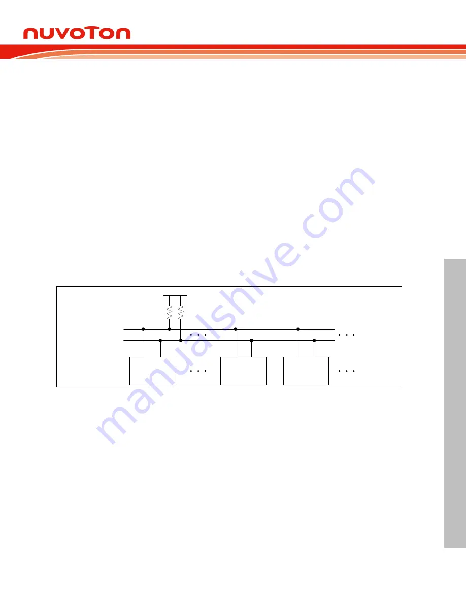
For a bi-directional transfer operation, the I2C0_SDA and I2C0_SCL pins should be open-drain pads.
This implements a wired-AND function, which is essential to the operation of the interface. A low level
on a I
2
C bus line is generated when one or more I
2
C d
evices output a “0”. A high level is generated
when all I
2
C devices output “1”, allowing the pull-up resistors to pull the line high. In MS51, user
should set output latches of I2C0_SCL and I2C0_SDA. As logic 1 before enabling the I
2
C function by
setting I2CEN.
SDA SCL
Slave Device
SDA SCL
Other MCU
SDA
SCL
V
DD
R
UP
R
UP
SDA SCL
ML51
Figure 6.10-1 I
2
C Bus Interconnection
The I
2
C is considered free when both lines are high. Meanwhile, any device, which can operate as a
master can occupy the bus and generate one transfer after generating a START condition. The bus
now is considered busy before the transfer ends by sending a STOP condition. The master generates
all of the serial clock pulses and the START and STOP condition. However if there is no START
condition on the bus, all devices serve as not addressed slave. The hardware looks for its own slave
address or a General Call address. (The General Call address detection may be enabled or disabled
by GC (I2CnADDRx.0).) If the matched address is received, an interrupt is requested.
Every transaction on the I
2
C bus is 9 bits long, consisting of 8 data bits (MSB first) and a single
acknowledge bit. The number of bytes per transfer (defined as the time between a valid START and
STOP condition) is unrestricted but each byte has to be followed by an acknowledge bit. The master
device generates 8 clock pulse to send the 8-bit data. After the 8
th
falling edge of the I2C0_SCL line,
the device outputting data on the I2C0_SDA changes that pin to an input and reads in an
acknowledge value on the 9
th
clock pulse. After 9
th
clock pulse, the data receiving device can hold
I2C0_SCL line stretched low if next receiving is not prepared ready. It forces the next byte transaction
suspended. The data transaction continues when the receiver releases the I2C0_SCL line.


