background image


- 51 - 

THROTTLE ADJUSTMENT 

ADJUSTMENT OF FLOW TO THE HYDRAULIC MOTOR 

 
To adjust the hydraulic motor’s flow rate, you must first depressurize the hydraulic 
system.  You will then need to remove the plug (AS) and the flat seal (a65) covering the 
throttle (a5).  You can then adjust the throttle using a slotted screwdriver (t22).  By 
turning the throttle counterclockwise, you will increase the flow rate to the hydraulic 
motor, thus increasing the lubricant flow rate.  Before starting the unit, re-install the plug 
and flat seal. 
 
Use the visible eccentric shaft (a56) to check for proper working order.  The number of 
revolutions of the eccentric shaft or the number of strokes of the delivery plunger 
enables you to calculate the precise delivery rate. 


Содержание G015

Страница 1: ...lically Actuated 7550 Independence Drive Walton Hills OH 44146 5541 Phone 440 232 7900 Toll free 800 225 4379 Fax 440 232 6294 Copyright 2019 NPK Construction Equipment Inc www npkce com G025 9600g Ha...

Страница 2: ...INSTALLATION TIPS 16 HOSE INSTALLATION TIPS 17 INSTALLATION INSTRUCTIONS 18 G015 18 For NPK 500 to 1300 ft lb class hammers with fixed hammer port connections 18 For NPK 500 to 1300 ft lb class hammer...

Страница 3: ...NT OF THE LUBRICANT RELIEF VALVE 48 PUMP CARTRIDGE TEST PROCEDURE 49 REPLACEMENT OF THE PUMP CARTRIDGE 50 THROTTLE ADJUSTMENT 51 ADJUSTMENT OF FLOW TO THE HYDRAULIC MOTOR 51 KEYWORDS FOR COMMON G015 A...

Страница 4: ...ed The NPK AUTO LUBE system is comprised of the grease pump assembly adapter fittings and hoses at the pump hammer and hammer top bracket The grease line length varies according to the NPK hammer size...

Страница 5: ...eader to situations which if not avoided could result in equipment damage Keep all decals clean and visible NPK will provide replacement NPK decals free of charge as needed Keep personnel and bystande...

Страница 6: ...ASE CARTRIDGE a56 ECCENTRIC SHAFT a57 FILTER ORIFICE ASSEMBLY a58 HYDRAULIC MOTOR a59 MAIN HOUSING 18 GREASE OUTLET PORT 30 GREASE FITTING 126 INLET HYDRAULIC PORT 127 RETURN HYDRAULIC PORT 155 INSPEC...

Страница 7: ...ANGE 32 158 F 32 158 F 0 70 C 0 70 C Eccentric speed can be adjusted with throttle PUMPING ELEMENT G015 G025 DELIVERY RATE PER STROKE 004 oz 12 cm 004 oz 12 cm STROKES AT STANDARD 14 per minute 14 per...

Страница 8: ...7 GREASE PUMP ASSEMBLY G015 MOUNTING SPECIFICATIONS G025 MOUNTING SPECIFICATIONS...

Страница 9: ...t The NPK hammer mounted auto lube system is connected to the hydraulic system of the carrier unit via the pressure line 6 of the hammer to port POIL 126 of the lube pump housing a59 The hydraulic oil...

Страница 10: ...via the pressure channel An integrated check valve prevents the lubricant from being fed back into the grease pump cartridge Transparent plastic reusable cartridges a54 serve as a storage reservoir fo...

Страница 11: ...ort block The NPK hammer mounted auto lube system is connected to the hydraulic system of the carrier unit via the pressure line 6 of the hammer to port POIL 126 of the lube pump housing a59 The hydra...

Страница 12: ...integrated check valve prevents the lubricant from being fed back into the grease pump cartridge To protect the Auto Lube system the pump includes a relief valve a3 which opens at 4060 psi 280 bars Th...

Страница 13: ...g operation In the case of wear of the pumping element grease pump cartridge the grease comes out of the lateral relief hole 156 If there is failure of the hydraulic system or the Auto Lube pump a gre...

Страница 14: ...shaft As the eccentric shaft revolves it strokes the delivery plunger which is part of the pumping element a11 The stroking of the delivery plunger creates suction and delivery of the lubricant An in...

Страница 15: ...the delivery plunger which is part of the pumping element a11 The stroking of the delivery plunger creates suction and delivery of the lubricant An integrated check valve k3 prevents the lubricant fr...

Страница 16: ...ication Place checked parts in a clean area to prevent damage or contamination Do not remove protective packaging from parts until ready for use The Hammer Mounted Grease Pump Assembly can be installe...

Страница 17: ...ing groove BA to hold the oring in place before assembly Make sure the fitting face and the tube or hose face are parallel as displayed above in example 158 PARALLEL 159 NON PARALLEL Torque fittings a...

Страница 18: ...twisted hose can result in premature hose failure or loose connections Attach both ends of hose to its connection point Let the hose find its natural position 103 then tighten both ends of the hose Us...

Страница 19: ...either dirt nor any other type of contamination may fall into the intake area below the cartridge when the cartridge is being re filled 2 Remove the existing adapter fittings from the grease pump asse...

Страница 20: ...Bolt the grease pump FZ to its mounting plate using the two hex head cap screws AF1 NPK part number G025 4530 and washers U NPK part number G025 4700 Using high strength thread adhesive torque the he...

Страница 21: ...te to the hammer pressure inlet port Route return hose a64 from port ROIL on the grease pump through the side plate hole to the hammer return port 8 Fill grease line before installation See AUTO LUBE...

Страница 22: ...hammers with fixed hammer port connections 10 Install the cover plate YY over the grease pump assembly FZ Use the four hex head cap screws AF2 to secure cover to the pump mounting plate Using a high s...

Страница 23: ...either dirt nor any other type of contamination may fall into the intake area below the cartridge when the cartridge is being re filled 2 Remove the existing adapter fittings from the grease pump asse...

Страница 24: ...G025 4530 and washers U NPK part number G025 4700 Using high strength thread adhesive torque the hex head cap screws to 80 ft lbs 110Nm NOTE Washers G025 4700 must be installed per fig 1 Ref a and b...

Страница 25: ...63 from port POIL on the grease pump FZ through the hole in the hammer bracket side plate to the hammer pressure inlet port Route the return hose a64 from port ROIL on the grease pump through the side...

Страница 26: ...nation may fall into the intake area below the cartridge when the cartridge is being re filled 2 Remove the existing adapter fittings from the grease pump assembly Install one ORFS adapter fitting g19...

Страница 27: ...nstall the hammer into the bracket Bolt the grease pump FZ to its mounting plate a28 using the two hex head cap screws AF1 NPK part number G025 4530 and washers U NPK part number G025 4700 Using high...

Страница 28: ...iscard b Install the special adapter tee fittings a62 into the top bracket joint fittings m18a m18b Reconnect the hammer hoses m5 and m6 c Install straight fitting g19 into the special adapter fitting...

Страница 29: ...ose from pressure side joint fitting m18a through top bracket burnout to port labeled POIL on the grease pump FZ 5 2 For units with NPT style joint fittings a Disconnect the hammer hoses m5 and m6 fro...

Страница 30: ...e joint fittings a18a and a18b Reconnect the hammer hoses m5 and m6 d Install hydraulic hose a64 Route hose from return side joint fitting m18b through top bracket burnout to port labeled ROIL on the...

Страница 31: ...that include joint fittings 6 Install the supplied straight adapter fitting f1 into the hammer grease port 26 DO NOT install the above fitting into the hammer s air connection port 17 It is used in u...

Страница 32: ...the return hose a64 from port ROIL on the grease pump through the inside hammer and top brackets burnouts to the return side joint fitting m18b adapter fitting 8 Fill the grease line before installat...

Страница 33: ...assembly Install one ORFS adapter fitting g19 NPK part number L1213 6600 into the port labeled POIL 126 and one check valve k3b NPK part number G025 6300 into port ROIL 127 Plug g12 port PGREASE Remov...

Страница 34: ...orque the hex head cap screws to 80 ft lbs 110Nm NOTE Washers G025 4700 must be installed per fig 1 Ref a and b angles 5 Remove the plug from the hammer Auto Lube port 26 and discard Install adapter e...

Страница 35: ...hammer swivel fitting and connect to the grease outlet port 18 on the side of the grease pump assembly FZ 7 1 For units with SAE style joint fittings a Disconnect the hammer hoses m5 and m6 from the t...

Страница 36: ...the opposite port d Install hose line a64 Route hose from return side joint fitting m18b through top bracket burnout to port labeled ROIL on the grease pump FZ e Install hose line a63 Route hose from...

Страница 37: ...ttings g19 into the special elbows a88 c Install special elbows a88a and a88b into the joint fittings a18a and a18b Reconnect the hammer hoses m5 and m6 d Install hydraulic hose a64 Route hose from re...

Страница 38: ...e Install hydraulic hose a63 Route hose from pressure side joint fitting m18a through top bracket burnout to port labeled POIL on the grease pump 8 Wrap hydraulic lines a63 and a64 together using a p...

Страница 39: ...n severe galling of the tool and tool bushing PRIMING THE GREASE LINE 1 Place the hammer in a vertical position applying enough down force to push the tool up into the hammer 2 Turn the machine off 3...

Страница 40: ...grease pump assembly 7 Re attach the grease line 29 to the hammer KK 8 Pump twenty more shots of grease using the grease gun t37 or power greaser into the pump assembly FZ This will prime the hammer c...

Страница 41: ...urn the throttle adjustment approximately 1 1 2 turns counterclockwise Start hydraulic system then re adjust the throttle to the proper speed when the unit is working again Hydraulic motor faulty Repl...

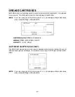
Страница 42: ...ered with these units contact NPK 1 800 225 4379 CARTRIDGE a54 TYPE S STANDARD GREASE TYPE NPK CHISEL PASTE CAPACITY 14 OZ 400 g CARTRIDGE ADAPTER G025 ONLY The NPK G025 grease pump only uses an adapt...

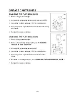
Страница 43: ...ted below the adapter in the pump housing is in good condition If there is damage to the seal replace it at this time See CHANGING THE FLAT SEAL REASSEMBLY 1 Inspect the lubricant passage 176 for cont...

Страница 44: ...o ring then install 5 Re insert the grease cartridge CHANGING THE FLAT SEAL G025 1 Remove the grease cartridge 2 Remove the cartridge adapter a53 see CHANGING THE CARTRIDGE ADAPTER 3 Using a pick rem...

Страница 45: ...NG THE FLAT SEAL 3 Inspect the lubricant passage for contamination 4 Apply a light coat of grease to the o ring RR located in the pump housing a59 then install 5 To accelerate priming first remove the...

Страница 46: ...rtridge follower piston a66 press the grease 28 out 3 16 3 8 5 10 mm 6 Next insert the cartridge into the cartridge adapter by pressing it slightly then threading it in by hand DO NOT OVERTIGHTEN NOTE...

Страница 47: ...NPK part number G025 8055 onto the empty grease cartridge a54e 2 Push nozzle t69 of the grease gun into the cartridge re fill adapter t70 3 Pump grease into empty cartridge until the follower piston...

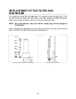
Страница 48: ...thrust piece a67 oring RR sealing ring a69 and strainer a60 Use a slotted screwdriver t22 to remove the diaphragm a61 NOTE Upon re installation make sure that the sealing edge of the diaphragm is not...

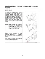
Страница 49: ...ug AS using a hex key wrench t25 Then using a ratchet t67 and 9mm socket t24 remove the relief valve cartridge assembly bs25 NOTE When installing the assembly make sure that the ball bs31 plunger c19...

Страница 50: ...G025 5075 PROCEDURE 1 Remove hydraulic motor a58 from the pump assembly FZ 2 Install a grease cartridge Make sure flat seal is in place 3 Install driveshaft t77 into drill motor t76 Couple opposite e...

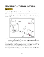
Страница 51: ...pump cartridge a11 NOTE When installing the new pump cartridge be cautious that no dirt gets into the pump Also the key c7 located on the pump cartridge housing must be in the groove in the housing T...

Страница 52: ...st the throttle using a slotted screwdriver t22 By turning the throttle counterclockwise you will increase the flow rate to the hydraulic motor thus increasing the lubricant flow rate Before starting...

Страница 53: ...si 300 bar gr04 3625 psi 250 bar gr05 2900 psi 200 bar gr06 2175 psi 150 bar gr07 Turns of the throttle adjustment NOTE Adjustment of the eccentric s revolutions is made by an adjusting throttle Each...

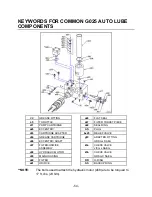
Страница 54: ...6 ECCENTRIC AS PLUG a54 GREASE CARTRIDGE g19 ADAPTER FITTING a56 ECCENTRIC SHAFT ORSm x SAEm a57 FILTER ORIFICE k3a CHECK VALVE ASSEMBLY JICm x SAEm a58 HYDRAULIC MOTOR k3b CHECK VALVE a59 MAIN HOUSIN...

Страница 55: ...a53 CARTRIDGE ADAPTER bs25 RELIEF VALVE a54 GREASE CARTRIDGE g19 ADAPTER FITTING a56 ECCENTRIC SHAFT ORSm x SAEm a57 FILTER ORIFICE k3a CHECK VALVE ASSEMBLY JICm x SAEm a58 HYDRAULIC MOTOR k3b CHECK V...

Страница 56: ...MON HAMMER MOUNTED AUTO LUBE HYDRAULIC MOTOR COMPONENTS c7 KEY hm2 DRIVE GEAR hm3 DRIVEN GEAR hm6 SHAFT SEAL hm9 WASHER hm16 MOTOR END CAP hm23 GEAR HOUSING hm28 BUSHING K DOWEL PIN OO CAP SCREW RR O...

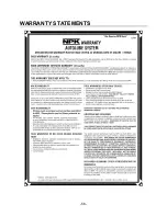
Страница 57: ...56 WARRANTY STATEMENTS...

Страница 58: ...57 WARRANTY STATEMENTS...

Страница 59: ...58 WARRANTY STATEMENTS...

Страница 60: ...Copyright 2019 NPK Construction Equipment Inc www npkce com G025 9600g Hammer Mounted Auto Lube System 11 19...

Отзывы: