- 13 -
FUNCTIONAL DESCRIPTION
G015
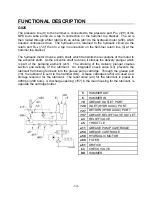
The pressure line (
6
) to the hammer is connected to the pressure port P
OIL
(
126
) of the
NPK Auto Lube pump via a tap in connection on the hammer top bracket. The oil is
then routed through a filter (a60) with an orifice (a61) to the hydraulic motor (a58), which
ensures continuous drive. The hydraulic oil is returned to the hydraulic circuit via the
return port R
OIL
(
127
) then to a tap in connection on the hammer return line (
5
) at the
hammer top bracket.
The hydraulic motor drives a worm shaft, which transmits the revolutions of the motor to
the eccentric shaft. As the eccentric shaft revolves, it strokes the delivery plunger which
is part of the pumping element (a11). The stroking of the delivery plunger creates
suction and delivery of the lubricant. An integrated check valve (k3) prevents the
lubricant from being fed back into the grease pump cartridge. Through the grease port
(
18
), the lubricant is sent to the hammer (KK). Grease cartridges (a54) are used as a
storage reservoir for the lubricant. A discharge opening (
157
) in the main housing for
the lubricant, is opposite the cartridge holder.
5
HAMMER OUT
6
HAMMER IN
18
GREASE OUTLET PORT
126
INLET (HYDRAULIC) PORT
127
RETURN (HYDRAULIC) PORT
157
GREASE OUTLET
a5
THROTTLE
a11
GREASE PUMP CARTRIDGE
a54
GREASE CARTRIDGE
a58
HYDRAULIC MOTOR
a60
FILTER
a61
ORIFICE
k3
CHECK VALVE
KK
HAMMER
Содержание G015
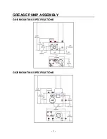
Страница 8: ...7 GREASE PUMP ASSEMBLY G015 MOUNTING SPECIFICATIONS G025 MOUNTING SPECIFICATIONS...
Страница 57: ...56 WARRANTY STATEMENTS...
Страница 58: ...57 WARRANTY STATEMENTS...
Страница 59: ...58 WARRANTY STATEMENTS...
Страница 60: ...Copyright 2019 NPK Construction Equipment Inc www npkce com G025 9600g Hammer Mounted Auto Lube System 11 19...

