CONNECTING
PAGE
|
29
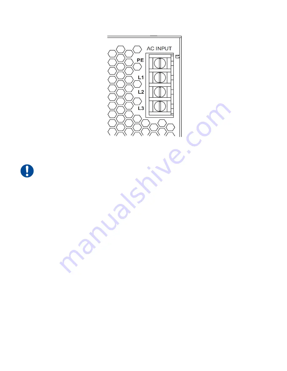
Figure 1-9 PS-401 input section
Important Note: Because AC input connections and requirements vary from facility to facility,
customers must provide the AC power cable or wiring. AC input connections to the PS-401 DC
power supply are made using a four-position terminal strip with M4 screw terminals on 13.0 mm centers.
To connect three-phase AC input power, refer to Figure 1-9 and perform the following steps:
1
Follow your facility’s Lockout/Tagout procedures and verify that input AC voltage to the DC
power supply is physically locked out or disconnected.
2
Connect the ground (earth) wire, typically green, to the input terminal labeled PE.
3
Connect the first three-phase hot wire, typically black, to the input terminal labeled L1.
4
Connect the second three-phase hot wire, typically red, to the input terminal labeled L2.
5
Connect the third hot wire, typically blue, to the input terminal labeled L3.
DC power/DC voltage sense cables
To connect DC power and the DC voltage sense cables between your i401 laser and PS-401 DC power
supply, refer to Figure 1-10 and Figure 1-11 and perform the following steps:
Содержание i401
Страница 1: ...ENGINEERED BY SYNRAD i401 Laser User Manual...
Страница 43: ...I401 LABEL LOCATIONS PAGE 43 i401 label locations Figure 2 1 Hazard label locations...
Страница 49: ...DECLARATION OF CONFORMITY PAGE 49 Declaration of conformity Figure 2 2 i401 Declaration of conformity...
Страница 97: ...I401 OUTLINE MOUNTING DRAWINGS PAGE 97 Figure 4 29 I401 outline mounting dimensions mounting feet removed...
Страница 98: ...I401 PACKAGING INSTRUCTIONS PAGE 98 i401 packaging instructions Figure 4 30 i401 packaging instructions...
Страница 132: ...INDEX PAGE 11...


