Chapter 3: Tuning and Testing Procedures
© 2019 Cutting Edge Optronics
30
Patara II and Iklwa II Service Manual
SHG Crystal Replacement and Alignment
1.
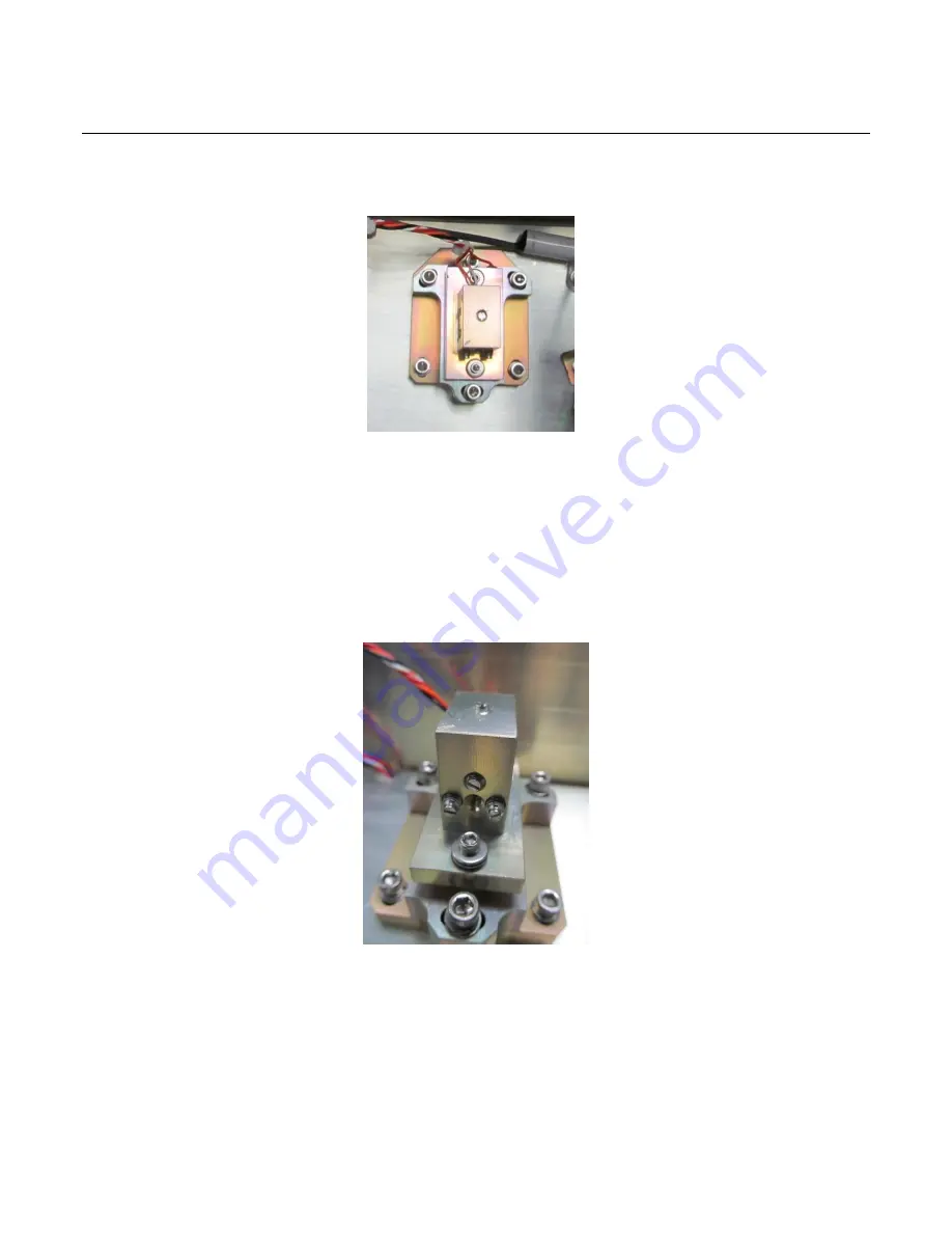
Disconnect TEC control cable and cut the cable tie. Remove the top crystal
mount by loosening the three # 8 screws (see
Figure 2-22
below).
Figure 2-22: SHG Mount Location
2.
Carefully remove the top mount with the crystal from the laser enclosure
Leave the base in place. If replacing the entire second harmonic generator
(SHG) assembly (HG24-0011), proceed to step 14.
3.
Loosen all 4 ball plunger screws as shown in
Figure 2-23
. Use tweezers to
carefully remove the conductive copper block, aluminum load spreader, two
macor insulators and SHG crystal seen in
Figure 2-24
. Discard used indium
foil.
Figure 2-23: Ball Plunger Screw Locations
4.
Cut 0.002" thick indium foil into (2) 4x9mm pieces, and .010" thick indium
foil into (1) 6 x 15mm piece.
5.
Press one of the 0.002" pieces onto the bottom (side opposite the arrow on the
crystal) of the new crystal, making sure it is centered on the crystal and none
of the indium is hanging over the edge.


