Page
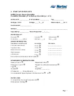
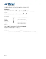
2. START-UP CHECK LISTS
NHRS Electric Steam Humidifier
Humidifier Mandatory Pre-Start-up Checklist (p.1 of 3)
Unit Serial #:
____________
# of humidifiers:
____________
Tag:
_____________
Unit type:
NHRS
Voltage:
_____V/___ph
Steam output:
____lbs./hr
Customer/Job:
_______________
Address:
____________________________________________________________________
Inspected by:
____________
Date of inspection:
___/___/___
WATER QUALITY:
Well water
City water
Softened water
Conductivity: _______mhmos
Hardness: _____gr.
Silica____ppm
HUMIDIFIER MOUNTING:
Clearances around the unit:
Acceptable
Obstruction
Front (door opens freely?)
3ft min
__________________
Top (steam lines)
1ft min
____________________
Bottom (fill, drain, controls)
1ft min
____________________
Right (main pwr)
3ft min
____________________
Left (main pwr)
2” min
____________________
Ensure the scale tank bracket is locked in place
STEAM LINES: CONDENSATE LINES:
Slope up 2” per 12”
Slopped back to drain
Slope down ½” per 12”
Trapped 2” more than static duct pressure
Traps
Size _______
Insulated
Length/Size ____________
90º elbows qty: ____ 45 deg. Elbows qty: ____
Can condensate be trapped anywhere in the steam line? Yes
no
WATER LINES:
½” at max 4ft from the unit -3/8” connection at fill
Water pressure: 30-80psig
Содержание NH Series
Страница 4: ......
Страница 6: ...Page 1 10 00 INTRODUCTION ...
Страница 7: ...Page 2 Figure 1 NHRS ...
Страница 11: ...Page 6 Figure 6 Typical NHRS Installation Sheet 1 of 2 ...
Страница 12: ...Page 7 Figure 7 Typical NHRS Installation Sheet 2 of 2 ...
Страница 13: ...Page 8 THIS PAGE INTENTIONALLY LEFT BLANK ...
Страница 14: ...Page 9 10 10 INSTALLATION PROCEDURES ...
Страница 17: ...Page 12 Figure 1 Plumbing Connections ...
Страница 23: ...Page 18 Figure 4 Steam Run and Condensate Return Installation Guidelines 1 of 2 ...
Страница 24: ...Page 19 Figure 5 Steam Run and Condensate Return Installation Guidelines 2 of 2 ...
Страница 28: ...Page 23 Figure 7 On Off Guidelines and Low Voltage Terminal Strip 254 8731 ...
Страница 29: ...Page 24 Figure 8 NORTEC Control Guidelines and Wiring Optional ...
Страница 31: ...Page 26 Figure 10 NORTEC Humidity Transducer Guidelines and Wiring Option ...
Страница 41: ...Page 36 Figure 22 Typical SAM e Duct Installation ...
Страница 45: ...Page 40 Figure 25 SAM e Drain Water Cooling ...
Страница 49: ...Page 44 THIS PAGE INTENTIONALLY LEFT BLANK ...
Страница 50: ...Page 45 10 20 OPERATION ...
Страница 60: ...Page 55 Figure 2 Drain Interval Settings ...
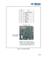
Страница 63: ...Page 58 Figure 3 Control Signal Setting ...
Страница 65: ...Page 60 THIS PAGE INTENTIONALLY LEFT BLANK ...
Страница 66: ...Page 10 30 MAINTENANCE PROCEDURES ...
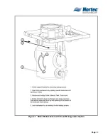
Страница 69: ...Page 6 Figure 1 Minor Maintenance with Scale Management Option ...
Страница 72: ...Page 6 10 40 TROUBLESHOOTING ...
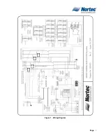
Страница 75: ...Page Figure 1 Wiring Diagram ...
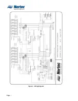
Страница 76: ...Page Figure 2 Wiring Diagram ...
Страница 81: ...Page 7 THIS PAGE INTENTIONALLY LEFT BLANK ...
Страница 82: ...Page 7 10 50 TECHNICAL ...
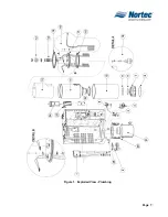
Страница 83: ...Page 7 Figure 1 Exploded View Plumbing ...
Страница 84: ...Page 7 Table 1 Exploded View Plumbing ...
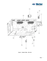
Страница 85: ...Page Figure 2 Exploded View Electrical ...
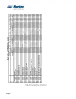
Страница 86: ...Page Table 2 Exploded View Electrical ...

