Page
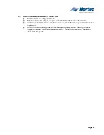
(f) Confirm that the high voltage feed to the unit is off then remove the high
voltage wires that connect to the top of the steam cylinder.
NOTE
The heating elements will not be affected if they are connected to different power
lines when reinstalled.
(g) Using a slotted screwdriver loosen the gear clamps that hold the steam line in
place.
(h) Remove the steam line.
(i) Remove the Zip Tie cylinder restraint.
(j) Lift the cylinder upward then out of the front of the unit.
CAUTION
BE EXTREMELY CAREFULL WHEN HANDLING THE STEAM CYLINDER. IF
IT IS DROPPED AND DAMAGED THERE IS A GOOD CHANGE IT WILL NOT
SEAL PROPERLY AND THE ENTIRE CYLINDER WILL NEED TO BE
REPLACED.
(k) Remove the clamp at the top of the cylinder.
(l) Remove the tank lid with elements attached.
(m) Remove all scale from the tank.
(n) Inspect the heating elements for damage.
(o) Re-install the equipment in the reverse order.
(p) Turn power and water supplies back on to the unit.
(q) Turn on the unit and carryout the steps of the visual inspection once more.
Содержание NH Series
Страница 4: ......
Страница 6: ...Page 1 10 00 INTRODUCTION ...
Страница 7: ...Page 2 Figure 1 NHRS ...
Страница 11: ...Page 6 Figure 6 Typical NHRS Installation Sheet 1 of 2 ...
Страница 12: ...Page 7 Figure 7 Typical NHRS Installation Sheet 2 of 2 ...
Страница 13: ...Page 8 THIS PAGE INTENTIONALLY LEFT BLANK ...
Страница 14: ...Page 9 10 10 INSTALLATION PROCEDURES ...
Страница 17: ...Page 12 Figure 1 Plumbing Connections ...
Страница 23: ...Page 18 Figure 4 Steam Run and Condensate Return Installation Guidelines 1 of 2 ...
Страница 24: ...Page 19 Figure 5 Steam Run and Condensate Return Installation Guidelines 2 of 2 ...
Страница 28: ...Page 23 Figure 7 On Off Guidelines and Low Voltage Terminal Strip 254 8731 ...
Страница 29: ...Page 24 Figure 8 NORTEC Control Guidelines and Wiring Optional ...
Страница 31: ...Page 26 Figure 10 NORTEC Humidity Transducer Guidelines and Wiring Option ...
Страница 41: ...Page 36 Figure 22 Typical SAM e Duct Installation ...
Страница 45: ...Page 40 Figure 25 SAM e Drain Water Cooling ...
Страница 49: ...Page 44 THIS PAGE INTENTIONALLY LEFT BLANK ...
Страница 50: ...Page 45 10 20 OPERATION ...
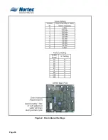
Страница 60: ...Page 55 Figure 2 Drain Interval Settings ...
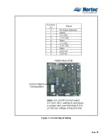
Страница 63: ...Page 58 Figure 3 Control Signal Setting ...
Страница 65: ...Page 60 THIS PAGE INTENTIONALLY LEFT BLANK ...
Страница 66: ...Page 10 30 MAINTENANCE PROCEDURES ...
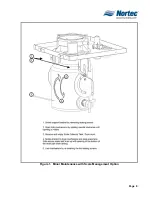
Страница 69: ...Page 6 Figure 1 Minor Maintenance with Scale Management Option ...
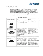
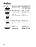
Страница 72: ...Page 6 10 40 TROUBLESHOOTING ...
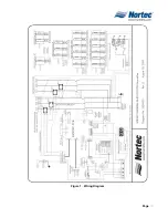
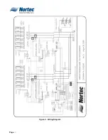
Страница 75: ...Page Figure 1 Wiring Diagram ...
Страница 76: ...Page Figure 2 Wiring Diagram ...
Страница 81: ...Page 7 THIS PAGE INTENTIONALLY LEFT BLANK ...
Страница 82: ...Page 7 10 50 TECHNICAL ...
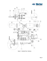
Страница 83: ...Page 7 Figure 1 Exploded View Plumbing ...
Страница 84: ...Page 7 Table 1 Exploded View Plumbing ...
Страница 85: ...Page Figure 2 Exploded View Electrical ...
Страница 86: ...Page Table 2 Exploded View Electrical ...


