Page 41
4. BLOWER PACKS (BOBP, RMBP)
WARNING
STEAM DISTRIBUTOR ON THE BUILT-ON AND REMOTE MOUNTED BLOWER
PACKS HAVE A HOT SURFACE THAT COULD RESULT IN BURNS IF
TOUCHED. NORTEC RECOMMENDS MOUNTING AT LEAST 8 FEET ABOVE
THE FLOOR.
A. BLOWER PACKS
(1) Optional blower packs are used to distribute steam to localized areas such as
computer rooms or in areas that do not have built-in air distribution systems.
(2) Blower packs are available detached, field piped, and wired to the humidifier RMBP
or separate power source. See Figure 26.
(3) Blower packs consist of a steel cabinet containing: 3 axial blowers with finger guards
powered by 120VAC or line voltage humidifiers, built-in multi-tap transformers (when
necessary), fuse, high temperature plastic distributor with stainless steel lid,
horizontal and vertical adjustment knobs for directional control, built-in thermostat to
active blowers, and safety loop relay.
(4) Refer to Table 7 for ceiling and frontal clearances required for blower packs.
Dimensions apply to both built-on and remote mounted blower packs.
(5) Mount remote blower packs with clearances as recommended in Table 7.
Содержание NH Series
Страница 4: ......
Страница 6: ...Page 1 10 00 INTRODUCTION ...
Страница 7: ...Page 2 Figure 1 NHRS ...
Страница 11: ...Page 6 Figure 6 Typical NHRS Installation Sheet 1 of 2 ...
Страница 12: ...Page 7 Figure 7 Typical NHRS Installation Sheet 2 of 2 ...
Страница 13: ...Page 8 THIS PAGE INTENTIONALLY LEFT BLANK ...
Страница 14: ...Page 9 10 10 INSTALLATION PROCEDURES ...
Страница 17: ...Page 12 Figure 1 Plumbing Connections ...
Страница 23: ...Page 18 Figure 4 Steam Run and Condensate Return Installation Guidelines 1 of 2 ...
Страница 24: ...Page 19 Figure 5 Steam Run and Condensate Return Installation Guidelines 2 of 2 ...
Страница 28: ...Page 23 Figure 7 On Off Guidelines and Low Voltage Terminal Strip 254 8731 ...
Страница 29: ...Page 24 Figure 8 NORTEC Control Guidelines and Wiring Optional ...
Страница 31: ...Page 26 Figure 10 NORTEC Humidity Transducer Guidelines and Wiring Option ...
Страница 41: ...Page 36 Figure 22 Typical SAM e Duct Installation ...
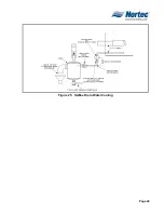
Страница 45: ...Page 40 Figure 25 SAM e Drain Water Cooling ...
Страница 49: ...Page 44 THIS PAGE INTENTIONALLY LEFT BLANK ...
Страница 50: ...Page 45 10 20 OPERATION ...
Страница 60: ...Page 55 Figure 2 Drain Interval Settings ...
Страница 63: ...Page 58 Figure 3 Control Signal Setting ...
Страница 65: ...Page 60 THIS PAGE INTENTIONALLY LEFT BLANK ...
Страница 66: ...Page 10 30 MAINTENANCE PROCEDURES ...
Страница 69: ...Page 6 Figure 1 Minor Maintenance with Scale Management Option ...
Страница 72: ...Page 6 10 40 TROUBLESHOOTING ...
Страница 75: ...Page Figure 1 Wiring Diagram ...
Страница 76: ...Page Figure 2 Wiring Diagram ...
Страница 81: ...Page 7 THIS PAGE INTENTIONALLY LEFT BLANK ...
Страница 82: ...Page 7 10 50 TECHNICAL ...
Страница 83: ...Page 7 Figure 1 Exploded View Plumbing ...
Страница 84: ...Page 7 Table 1 Exploded View Plumbing ...
Страница 85: ...Page Figure 2 Exploded View Electrical ...
Страница 86: ...Page Table 2 Exploded View Electrical ...

