Page 48
(b) Turn manual shut off valve to the flow through position providing water to the
unit.
(c) Switch on the external disconnect to provide voltage to the unit.
NOTE
If the Scale Management Option is used make sure the valve on the NHRS mineral
tank is closed
(d) Turn main power on via the rocker located on the keypad.
B.
SYSTEM START-UP TEST
(1)
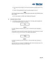
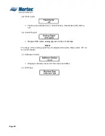
The NHRS humidifier carries out a system test. The display below appears and
the three LEDs light for approx. 3 seconds.
NOTES
If a fault is detected during the system test, a corresponding fault message is
triggered.
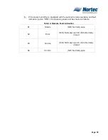
If the system test is successful, the steam cylinder fills up and a float test is carried
out (function check on the level unit). The display below appears.
NOTES
If a fault is detected during the float test, a corresponding fault message is
triggered.
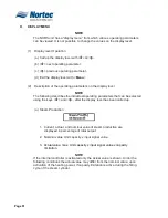
When both tests are successful, the NHRS will enter normal operating mode. The
display below appears and the green LED lights.
Содержание NH Series
Страница 4: ......
Страница 6: ...Page 1 10 00 INTRODUCTION ...
Страница 7: ...Page 2 Figure 1 NHRS ...
Страница 11: ...Page 6 Figure 6 Typical NHRS Installation Sheet 1 of 2 ...
Страница 12: ...Page 7 Figure 7 Typical NHRS Installation Sheet 2 of 2 ...
Страница 13: ...Page 8 THIS PAGE INTENTIONALLY LEFT BLANK ...
Страница 14: ...Page 9 10 10 INSTALLATION PROCEDURES ...
Страница 17: ...Page 12 Figure 1 Plumbing Connections ...
Страница 23: ...Page 18 Figure 4 Steam Run and Condensate Return Installation Guidelines 1 of 2 ...
Страница 24: ...Page 19 Figure 5 Steam Run and Condensate Return Installation Guidelines 2 of 2 ...
Страница 28: ...Page 23 Figure 7 On Off Guidelines and Low Voltage Terminal Strip 254 8731 ...
Страница 29: ...Page 24 Figure 8 NORTEC Control Guidelines and Wiring Optional ...
Страница 31: ...Page 26 Figure 10 NORTEC Humidity Transducer Guidelines and Wiring Option ...
Страница 41: ...Page 36 Figure 22 Typical SAM e Duct Installation ...
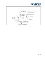
Страница 45: ...Page 40 Figure 25 SAM e Drain Water Cooling ...
Страница 49: ...Page 44 THIS PAGE INTENTIONALLY LEFT BLANK ...
Страница 50: ...Page 45 10 20 OPERATION ...
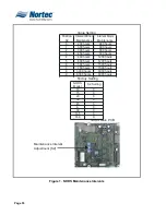
Страница 60: ...Page 55 Figure 2 Drain Interval Settings ...
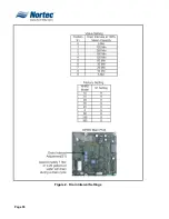
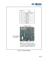
Страница 63: ...Page 58 Figure 3 Control Signal Setting ...
Страница 65: ...Page 60 THIS PAGE INTENTIONALLY LEFT BLANK ...
Страница 66: ...Page 10 30 MAINTENANCE PROCEDURES ...
Страница 69: ...Page 6 Figure 1 Minor Maintenance with Scale Management Option ...
Страница 72: ...Page 6 10 40 TROUBLESHOOTING ...
Страница 75: ...Page Figure 1 Wiring Diagram ...
Страница 76: ...Page Figure 2 Wiring Diagram ...
Страница 81: ...Page 7 THIS PAGE INTENTIONALLY LEFT BLANK ...
Страница 82: ...Page 7 10 50 TECHNICAL ...
Страница 83: ...Page 7 Figure 1 Exploded View Plumbing ...
Страница 84: ...Page 7 Table 1 Exploded View Plumbing ...
Страница 85: ...Page Figure 2 Exploded View Electrical ...
Страница 86: ...Page Table 2 Exploded View Electrical ...

