Page
14
F.
SCALE MANAGEMENT SYSTEM INSTALLATION
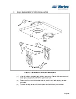
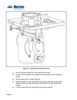
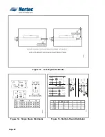
Figure 2. Installation of the Scale Tank Bracket
(1)
Line up holes in bracket with holes in drain pan. Fasten the bracket to the
drain pan using the four #10-32 nylon lock nuts.
(2)
Fasten the front of the bracket with the two #10-24 self tapping screws
provided.
(3)
The two locking screws for the bracket should already be installed.
Содержание NH Series
Страница 4: ......
Страница 6: ...Page 1 10 00 INTRODUCTION ...
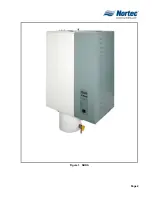
Страница 7: ...Page 2 Figure 1 NHRS ...
Страница 11: ...Page 6 Figure 6 Typical NHRS Installation Sheet 1 of 2 ...
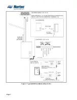
Страница 12: ...Page 7 Figure 7 Typical NHRS Installation Sheet 2 of 2 ...
Страница 13: ...Page 8 THIS PAGE INTENTIONALLY LEFT BLANK ...
Страница 14: ...Page 9 10 10 INSTALLATION PROCEDURES ...
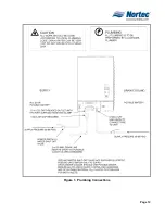
Страница 17: ...Page 12 Figure 1 Plumbing Connections ...
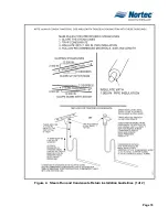
Страница 23: ...Page 18 Figure 4 Steam Run and Condensate Return Installation Guidelines 1 of 2 ...
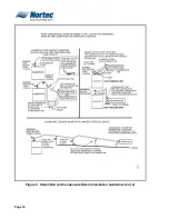
Страница 24: ...Page 19 Figure 5 Steam Run and Condensate Return Installation Guidelines 2 of 2 ...
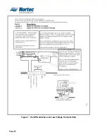
Страница 28: ...Page 23 Figure 7 On Off Guidelines and Low Voltage Terminal Strip 254 8731 ...
Страница 29: ...Page 24 Figure 8 NORTEC Control Guidelines and Wiring Optional ...
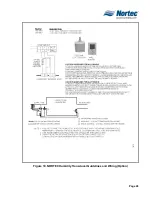
Страница 31: ...Page 26 Figure 10 NORTEC Humidity Transducer Guidelines and Wiring Option ...
Страница 41: ...Page 36 Figure 22 Typical SAM e Duct Installation ...
Страница 45: ...Page 40 Figure 25 SAM e Drain Water Cooling ...
Страница 49: ...Page 44 THIS PAGE INTENTIONALLY LEFT BLANK ...
Страница 50: ...Page 45 10 20 OPERATION ...
Страница 60: ...Page 55 Figure 2 Drain Interval Settings ...
Страница 63: ...Page 58 Figure 3 Control Signal Setting ...
Страница 65: ...Page 60 THIS PAGE INTENTIONALLY LEFT BLANK ...
Страница 66: ...Page 10 30 MAINTENANCE PROCEDURES ...
Страница 69: ...Page 6 Figure 1 Minor Maintenance with Scale Management Option ...
Страница 72: ...Page 6 10 40 TROUBLESHOOTING ...
Страница 75: ...Page Figure 1 Wiring Diagram ...
Страница 76: ...Page Figure 2 Wiring Diagram ...
Страница 81: ...Page 7 THIS PAGE INTENTIONALLY LEFT BLANK ...
Страница 82: ...Page 7 10 50 TECHNICAL ...
Страница 83: ...Page 7 Figure 1 Exploded View Plumbing ...
Страница 84: ...Page 7 Table 1 Exploded View Plumbing ...
Страница 85: ...Page Figure 2 Exploded View Electrical ...
Страница 86: ...Page Table 2 Exploded View Electrical ...


