Page 52
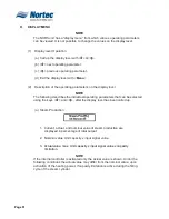
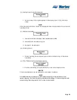
(b) Analog Input (humidity demand)
1. Current value of the signal applied to the analog input in [%] of its max.
value.
NOTE
If the internal controller is active the displayed value corresponds to the current air
humidity (%rh).
(c) Internal Controller
1.
Internal controller activated (”
on
”)/deactivated (”
off
”).
2. Activated with transducer signal.
3. Demand = de-activated.
(d) Working Hours
1. Total of working hours elapsed since initial commissioning of the steam
humidifier.
(e) Time Remaining to minor/major service
1. The time remaining (in hours) before the next minor/major service.
NOTE
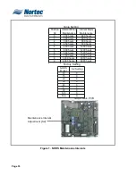
Time to maintenance can be adjusted to suit water conditions
NOTE
The stated times are based on 100% steam capacity. If the operation is at a
lesser capacity, the time should be extended accordingly. The servicing intervals
are set using the rota
ry switch “S2” on the control board.
Содержание NH Series
Страница 4: ......
Страница 6: ...Page 1 10 00 INTRODUCTION ...
Страница 7: ...Page 2 Figure 1 NHRS ...
Страница 11: ...Page 6 Figure 6 Typical NHRS Installation Sheet 1 of 2 ...
Страница 12: ...Page 7 Figure 7 Typical NHRS Installation Sheet 2 of 2 ...
Страница 13: ...Page 8 THIS PAGE INTENTIONALLY LEFT BLANK ...
Страница 14: ...Page 9 10 10 INSTALLATION PROCEDURES ...
Страница 17: ...Page 12 Figure 1 Plumbing Connections ...
Страница 23: ...Page 18 Figure 4 Steam Run and Condensate Return Installation Guidelines 1 of 2 ...
Страница 24: ...Page 19 Figure 5 Steam Run and Condensate Return Installation Guidelines 2 of 2 ...
Страница 28: ...Page 23 Figure 7 On Off Guidelines and Low Voltage Terminal Strip 254 8731 ...
Страница 29: ...Page 24 Figure 8 NORTEC Control Guidelines and Wiring Optional ...
Страница 31: ...Page 26 Figure 10 NORTEC Humidity Transducer Guidelines and Wiring Option ...
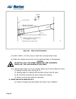
Страница 41: ...Page 36 Figure 22 Typical SAM e Duct Installation ...
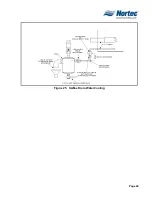
Страница 45: ...Page 40 Figure 25 SAM e Drain Water Cooling ...
Страница 49: ...Page 44 THIS PAGE INTENTIONALLY LEFT BLANK ...
Страница 50: ...Page 45 10 20 OPERATION ...
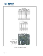
Страница 60: ...Page 55 Figure 2 Drain Interval Settings ...
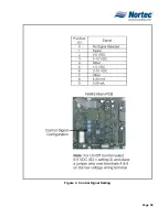
Страница 63: ...Page 58 Figure 3 Control Signal Setting ...
Страница 65: ...Page 60 THIS PAGE INTENTIONALLY LEFT BLANK ...
Страница 66: ...Page 10 30 MAINTENANCE PROCEDURES ...
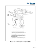
Страница 69: ...Page 6 Figure 1 Minor Maintenance with Scale Management Option ...
Страница 72: ...Page 6 10 40 TROUBLESHOOTING ...
Страница 75: ...Page Figure 1 Wiring Diagram ...
Страница 76: ...Page Figure 2 Wiring Diagram ...
Страница 81: ...Page 7 THIS PAGE INTENTIONALLY LEFT BLANK ...
Страница 82: ...Page 7 10 50 TECHNICAL ...
Страница 83: ...Page 7 Figure 1 Exploded View Plumbing ...
Страница 84: ...Page 7 Table 1 Exploded View Plumbing ...
Страница 85: ...Page Figure 2 Exploded View Electrical ...
Страница 86: ...Page Table 2 Exploded View Electrical ...


