Page
16
G.
STEAM LINES AND CONDENSATE RETURNS
(1)
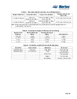
Tables 1 through 5 indicate what material and recommended length to use when
installing atmospheric steam lines. The lengths mentioned are equivalent feet
and therefore the full length of steam line includes the addition of the equivalent
length of all elbows and tees.
(2)
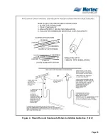
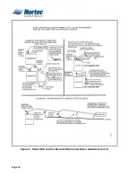
Figure 4 and Figure 5
illustrates the guidelines for installation, routing and
trapping of the steam lines and condensate returns.
(3)
Table 6 indicates steam outlet size of the humidifier and steam inlet size of the
distributor.
Содержание NH Series
Страница 4: ......
Страница 6: ...Page 1 10 00 INTRODUCTION ...
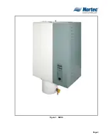
Страница 7: ...Page 2 Figure 1 NHRS ...
Страница 11: ...Page 6 Figure 6 Typical NHRS Installation Sheet 1 of 2 ...
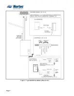
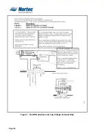
Страница 12: ...Page 7 Figure 7 Typical NHRS Installation Sheet 2 of 2 ...
Страница 13: ...Page 8 THIS PAGE INTENTIONALLY LEFT BLANK ...
Страница 14: ...Page 9 10 10 INSTALLATION PROCEDURES ...
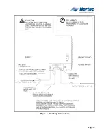
Страница 17: ...Page 12 Figure 1 Plumbing Connections ...
Страница 23: ...Page 18 Figure 4 Steam Run and Condensate Return Installation Guidelines 1 of 2 ...
Страница 24: ...Page 19 Figure 5 Steam Run and Condensate Return Installation Guidelines 2 of 2 ...
Страница 28: ...Page 23 Figure 7 On Off Guidelines and Low Voltage Terminal Strip 254 8731 ...
Страница 29: ...Page 24 Figure 8 NORTEC Control Guidelines and Wiring Optional ...
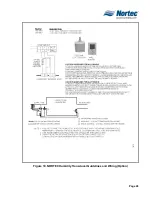
Страница 31: ...Page 26 Figure 10 NORTEC Humidity Transducer Guidelines and Wiring Option ...
Страница 41: ...Page 36 Figure 22 Typical SAM e Duct Installation ...
Страница 45: ...Page 40 Figure 25 SAM e Drain Water Cooling ...
Страница 49: ...Page 44 THIS PAGE INTENTIONALLY LEFT BLANK ...
Страница 50: ...Page 45 10 20 OPERATION ...
Страница 60: ...Page 55 Figure 2 Drain Interval Settings ...
Страница 63: ...Page 58 Figure 3 Control Signal Setting ...
Страница 65: ...Page 60 THIS PAGE INTENTIONALLY LEFT BLANK ...
Страница 66: ...Page 10 30 MAINTENANCE PROCEDURES ...
Страница 69: ...Page 6 Figure 1 Minor Maintenance with Scale Management Option ...
Страница 72: ...Page 6 10 40 TROUBLESHOOTING ...
Страница 75: ...Page Figure 1 Wiring Diagram ...
Страница 76: ...Page Figure 2 Wiring Diagram ...
Страница 81: ...Page 7 THIS PAGE INTENTIONALLY LEFT BLANK ...
Страница 82: ...Page 7 10 50 TECHNICAL ...
Страница 83: ...Page 7 Figure 1 Exploded View Plumbing ...
Страница 84: ...Page 7 Table 1 Exploded View Plumbing ...
Страница 85: ...Page Figure 2 Exploded View Electrical ...
Страница 86: ...Page Table 2 Exploded View Electrical ...

