


Page 25
K. OPTIONAL OUTDOOR TEMPERATURE RESET FUNCTION
NOTE
Order Outdoor Temperature sensor separately, Part Number #252-0263
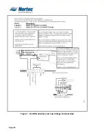
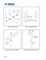
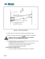
(1) Each humidistat and controller is equipped with an integrated reset function that
will lower the set point during cold weather operation. This will prevent
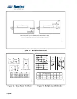
condensate from forming on the windows and building structures. Figure 9
illustrates how the setpoint-reset feature operates.
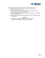
(2)
Removing the jumper from terminals 8 and 1 on the humidistat controller enables
this Outdoor Temperature Setback option. The Outdoor Temperature Sensor is
then wired to these terminals.
(3)
When the outdoor Temperature setback feature is in effect, the humidistat will
normally display the calculated setpoint limit based on the outdoor air
temperature. A snowflake will also be displayed to indicate cold weather
operation. When any key on the controller is pressed, the LCD screen will display
the customer specified setpoint for a short duration.
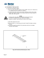
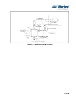
L.
HUMIDITY TRANSDUCER SIGNAL INSTALLATION
(1)
Figure 10 displays NORTEC optional humidity transducer installation.
Figure 9. Setpoint vs. Outdoor Temperature
Содержание NH Series
Страница 4: ......
Страница 6: ...Page 1 10 00 INTRODUCTION ...
Страница 7: ...Page 2 Figure 1 NHRS ...
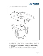
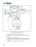
Страница 11: ...Page 6 Figure 6 Typical NHRS Installation Sheet 1 of 2 ...
Страница 12: ...Page 7 Figure 7 Typical NHRS Installation Sheet 2 of 2 ...
Страница 13: ...Page 8 THIS PAGE INTENTIONALLY LEFT BLANK ...
Страница 14: ...Page 9 10 10 INSTALLATION PROCEDURES ...
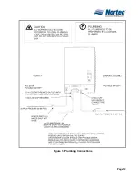
Страница 17: ...Page 12 Figure 1 Plumbing Connections ...
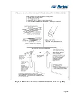
Страница 23: ...Page 18 Figure 4 Steam Run and Condensate Return Installation Guidelines 1 of 2 ...
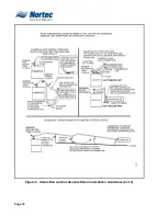
Страница 24: ...Page 19 Figure 5 Steam Run and Condensate Return Installation Guidelines 2 of 2 ...
Страница 28: ...Page 23 Figure 7 On Off Guidelines and Low Voltage Terminal Strip 254 8731 ...
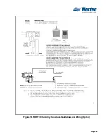
Страница 29: ...Page 24 Figure 8 NORTEC Control Guidelines and Wiring Optional ...
Страница 31: ...Page 26 Figure 10 NORTEC Humidity Transducer Guidelines and Wiring Option ...
Страница 41: ...Page 36 Figure 22 Typical SAM e Duct Installation ...
Страница 45: ...Page 40 Figure 25 SAM e Drain Water Cooling ...
Страница 49: ...Page 44 THIS PAGE INTENTIONALLY LEFT BLANK ...
Страница 50: ...Page 45 10 20 OPERATION ...
Страница 60: ...Page 55 Figure 2 Drain Interval Settings ...
Страница 63: ...Page 58 Figure 3 Control Signal Setting ...
Страница 65: ...Page 60 THIS PAGE INTENTIONALLY LEFT BLANK ...
Страница 66: ...Page 10 30 MAINTENANCE PROCEDURES ...
Страница 69: ...Page 6 Figure 1 Minor Maintenance with Scale Management Option ...
Страница 72: ...Page 6 10 40 TROUBLESHOOTING ...
Страница 75: ...Page Figure 1 Wiring Diagram ...
Страница 76: ...Page Figure 2 Wiring Diagram ...
Страница 81: ...Page 7 THIS PAGE INTENTIONALLY LEFT BLANK ...
Страница 82: ...Page 7 10 50 TECHNICAL ...
Страница 83: ...Page 7 Figure 1 Exploded View Plumbing ...
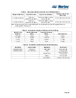
Страница 84: ...Page 7 Table 1 Exploded View Plumbing ...
Страница 85: ...Page Figure 2 Exploded View Electrical ...
Страница 86: ...Page Table 2 Exploded View Electrical ...


