background image

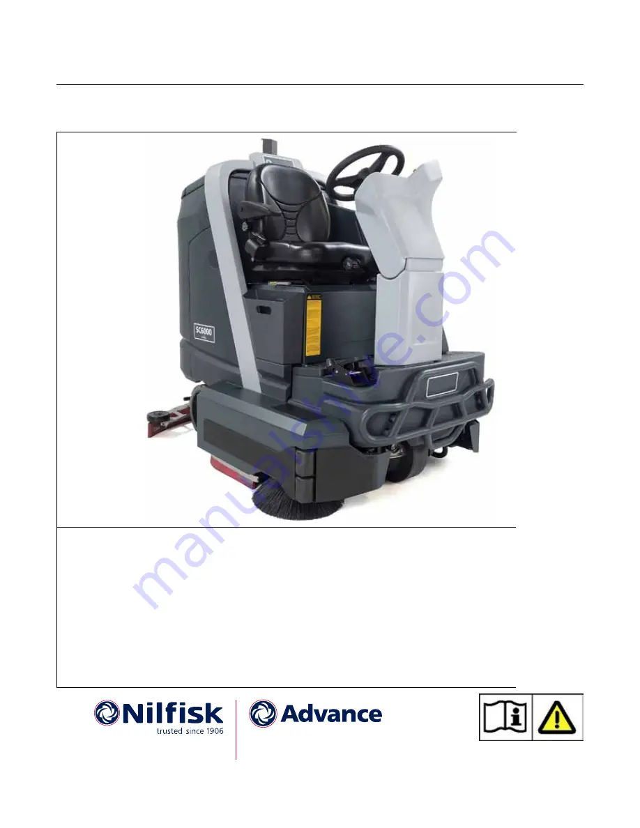
SC6000

June/2016  Form No. 56043174 

Service Manual

Advance Model Numbers: 

56116000 

SC6000 36C 

56116001 

SC6000 40D 

56116002 

SC6000 34D

Nilfisk Model Numbers: 

56116003 

SC6000 910C

56116004 

SC6000 1050D

56116005 

SC6000 860D

Language

Содержание SC6000 1050D

Страница 1: ...2016 Form No 56043174 Service Manual Advance Model Numbers 56116000 SC6000 36C 56116001 SC6000 40D 56116002 SC6000 34D Nilfisk Model Numbers 56116003 SC6000 910C 56116004 SC6000 1050D 56116005 SC6000 860D Language ...

Страница 2: ... Description 16 Functional Block Diagram 16 Wheel Drive Controller 17 Power Module 18 Main Machine Controller 19 Main Controller Operational Modes 20 Operational Mode Prerequisites 20 Control Panel 23 CAN Bus Communication 24 Component Locations 25 Main Machine Controller Programming 26 Service Mode Access 26 Menu Navigation 26 Programming Menu Outline 27 Hours Menu 28 Faults Menu 28 Keys Menu 28 ...

Страница 3: ...47 20 Wheel System Traction 48 Functional Description 48 Drive Motor 48 Drive Pedal Potentiometer 48 Drive Controller 49 Operational Mode Prerequisites 50 Troubleshooting 50 Drive Controller E4 Error Codes 50 Maintenance and Adjustments 53 Drive Pedal Neutral Adjustment 53 Removal and Installation 54 Drive Controller 54 Drive Wheel Assembly 55 Electromechanical Brake 58 Drive Tire 59 Specification...

Страница 4: ...ion 77 Common Schematic Symbols 78 Wiring Diagram 79 Wiring Harness Diagram 82 30 Solution System 84 Functional Description 84 Shutoff Valve 84 Solution Solenoid 84 Solution Level Sensors 84 Wash Hose Option 84 Dust Guard Option 85 EcoFlex Option 85 Operational Mode Prerequisites 86 Troubleshooting 87 Level Sensors 87 Resetting a Float Position 87 Detergent Pumps 88 Removal and Installation 88 Sol...

Страница 5: ...pecifications 116 Special Tools 116 Actuator Test Kit 116 38 Squeegee System 117 Functional Description 117 Squeegee Lift Actuator 117 Squeegee 118 Maintenance and Adjustment 118 Squeegee Blade Cleaning and Inspection 118 Squeegee Height and Tilt Adjustment 119 Actuator Limit Adjustment 120 Removal and Installation 122 Rear main Squeegee Blade Reversal or Replacement 122 Front Squeegee Blade Rever...

Страница 6: ...d 135 Beacon 135 Weight Kit 135 Foot Guard 135 Mop Holder 135 Wash Hose 136 Deluxe Seat 136 Overhead Guard 136 Heavy Duty Front Bumper 136 Onboard Charger 136 Battery Watering 136 Solution Autofill 137 Squeegee Guard 137 Headlights 137 Backup Alarm 137 Vac Wand 137 USB Power Port 137 TrackClean 138 Troubleshooting 138 ...

Страница 7: ... number that the manual applies to Compare the part number of the machine you are working on to the model numbers listed on the cover page to be sure you are using the correct manual Other Reference Manuals and Information Sources Document Name Document Number Document Type SC6000 Instructions for Use Nilfisk 56091168 Operator s Manual SC6000 Instructions for Use Advance 56091161 Operator s Manual...

Страница 8: ...ation shall not be performed by the owner or user without prior written approval from Nilfisk Inc Unapproved modifications will void the machine warranty and make the owner user liable for any consequential damages Nameplate The nameplate contains important identification information which will be needed when ordering parts The Model Number Part No and Serial Number of the machine are shown on the...

Страница 9: ...Do not operate the machine near toxic dangerous flammable and or explosive materials This machine is not suitable for collecting dangerous or hazardous materials In case of fire use a powder fire extinguisher not a water based extinguisher Do not use on surfaces having a gradient exceeding that marked on the machine While on ramps or inclines avoid sudden stops when loaded Avoid abrupt sharp turns...

Страница 10: ...hine is only approved for hard surface use Use brushes and pads supplied with the machine or those specified in the User Manual Using other brushes or pads could reduce safety Do not wash the machine with direct or pressurised water jets or with corrosive substances Do not allow the brush pad to operate while the machine is stationary to avoid damaging the floor Use only factory authorized parts a...

Страница 11: ...ne is not operational you must manually release the brake To release the brake move the release handle outward and insert an object such as a screw driver behind the lever to keep it deactivated Remove the squeegee from the machine This is required to access the rear hold down points and also protects the squeegee during loading unloading and transport If the loading unloading or transport operati...

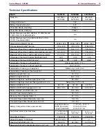
Страница 12: ...sport with weight kit Nilfisk only 20 9 11 8 Gradeability Transport without weight kit 18 5 10 5 Gradeability Cleaning with weight kit Nilfisk only 16 9 9 6 Gradeability Cleaning without weight kit 12 2 7 Machine Length inch cm 70 178 Machine Height inch cm 62 3 158 Machine Height w overhead guard inch cm 82 208 Machine Height w short overhead guard inch cm Nilfisk Only 78 75 200 Machine Width inc...

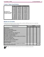
Страница 13: ...l environments may require service more often Maintenance Item Interval Daily Weekly Monthly Yearly Charge Batteries Check Clean Tanks Hoses Check Clean Rotate the Brushes Pads Check Clean the Squeegee Empty Clean Debris Catch Tray in Recovery Tank Check Clean the vacuum motor foam filter Clean Hopper on Cylindrical System Check Battery Cell Water Level does not apply to gel cell batteries Inspect...

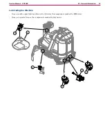
Страница 14: ...Manual SC6000 03 General Information Lubricating the Machine Once a month apply light machine oil to lubricate the components marked by B below Once per quarter Grease the components marked by A below A A B A A A ...

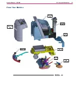
Страница 15: ...15 Service Manual SC6000 03 General Information Know Your Machine Recovery Tank Solution Tank Steering Column Side Doors Chassis Side Broom Scrub Deck Squeegee ...

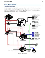
Страница 16: ...roller and the optional TrackClean Module Functional Block Diagram E2 Main Control Board E3 Power Module E4 Wheel Drive Controller K1 KSI Relay K2 Relay Enable Control K3 Relay Control Control Power Power CAN Bus Solution Solenoid Dust Guard Solenoid Horn Backup Alarm Headlight Detergent Pump 1 Detergent Pump 2 Solution Level Sensors Horn Switch Burst of Power Solution Switch Float Switch Side Bro...

Страница 17: ...y but it controls its own high power input through the K3 relay When the main machine controller has not energized the KSI relay the drive controller is off The drive controller also has 2 enabling inputs directly from the operator s seat switch and the E stop button If either one of these switches is open the drive is disabled but has power The drive controller receives its direction and speed co...

Страница 18: ...control The lower power outputs are reversing PWM control The power module is capable of monitoring the output amperage from each of the outputs and reporting this information to the main machine controller via the CAN Bus B J3 14 CAN1 H CAN1 L B J3 13 J3 4 J3 6 J3 3 J3 1 E3 POWER MODULE OPTION KSI J3 10 J3 11 J3 2 RIGHT DECK BRUSH IS REAR CYINDRICAL BRUSH LEFT DECK BRUSH IS FRONT CYLINDRICAL BRUS...

Страница 19: ...J1 22 J1 14 J1 13 J1 4 J1 16 J1 17 J1 18 J1 19 J1 3 J1 11 J1 21 J1 20 J TO 3C4 B TO 2B1 I TO 2B3 BLK BLK GRA GRA VIO BRN GRN BRN YEL BRN ORN YEL GRA BLK YEL BRN ORN BRN YEL RED ORN RED BLK TAN WHT WHT ORN BLK BLK ORN GRN BLU GRA BLK RED YEL WHT RED RED YEL BRN YEL BRN BLU RED BLK BLU BRN LVL 4 LVL 1 LVL 3 LVL 2 BLK WHT BLU GRA GRA GRN BLU BLU RED BLU RED BLU RED BLU RED GRA GRA BLK BLU YEL GRN RED...

Страница 20: ...own scrub solution and recovery Has exclamation triangle icon displayed Operational Mode Prerequisites Before the main controller can activate any of the operational modes it must first check that the appropriate prerequisites are met Scrub System Outputs Brush Motors M1 and M2 or Deck Actuator M7 seat switch must be closed to enter scrub mode No scrub system fault brush motors and actuator motor ...

Страница 21: ...second stage No RTF inhibit Not turned off with the membrane switch Not momentarily turned off by the solution timed off paddle switch input Spray wash pump M10 No spray wash pump M10 fault Solution tank is not empty Option Opt pump in configuration menu set to Spray Wash Detergent System outputs Detergent Pumps M8 and M9 Solution system is active EcoFlex is enabled in the configuration menu Not t...

Страница 22: ... Must be enabled in configuration menu Throttle command 0 Headlights LP1 and LP2 Headlight option set to Yes in configuration menu Always active Follows headlight membrane switch input Will start out on if Headlights set to on In the options menus Drive Controller outputs Drive wheel motor No interlock message from the main controller on the CAN bus only active during auto disc brush install mode ...

Страница 23: ...ng Menu Outline on page 27 One Touch Scrub F When the One Touch Scrub is selected the brushes and squeegee are lowered to the floor and the solution solenoid is briefly activated to pre wet the brushes The scrub solution vacuum and detergent EcoFlex models systems are all enabled and will start when the Drive Pedal is activated Solution Switch G The solution switch enables or disables the solution...

Страница 24: ... same time it is also monitoring the bus itself to detect if a higher priority message was being initiated at the same time The message with the higher priority level will have the bus high for the longest period and therefore that module knows that it is sending the highest priority message The other module ceases its transmission and waits until the bus is available again Most CAN Bus messages o...

Страница 25: ...04 Control System Component Locations KSI Relay SmartKey Reader Main Machine Controller E Stop Switch 10 Amp Breaker Drive Module Power Module K2 Power Relay K3 Drive Relay Battery Cable Power Jumper Bat Bat Bat Bat Motor U V W ...

Страница 26: ...he machine starts up and then can remove the key For a Nilfisk branded machine place a user or supervisor SmartKey in the key reader and then simultaneously press the Scrub Vacuum and Power switches to turn the machine on in service mode For an Advance branded machine a SmartKey is not required Simultaneously press the Scrub Vacuum and Power switches to turn the machine on in service mode Menu Nav...

Страница 27: ...ide Sweep Vac 1 Vac 2 M4 PWM Req M4 PWM Output M4 Amps M5 PWM Req M5 PWM Output M5 Amps M6 PWM Req M6 PWM Output M6 Amps M7 PWM Req M7 PWM Output M7 Amps M10 PWM Req M10 PWM Output M10 Amps Option Pump Deck Lift Squeegee E4 Drive Controller Speed mph kph Throttle Throttle Voltage Current RPM Phase A rpm Phase B rpm Interlock Seat Switch E Stop M11 Temperature M11 Temp Cutback E4 Temperature E4 Tem...

Страница 28: ...or diagnosed Keys Menu The Keys menu displays information about the current key and also permits the addition or deletion of authorized user keys User level keys blue keys can be authorized or de authorized to operate the machine However if no keys have been authorized then all user keys will be accepted Every key has a Hard coded ID number HID This is the serial number for the key and is also imp...

Страница 29: ... Stop This is the input signal from the E stop switch The E stop switch is active open i e normally closed so this input should normally be a 1 unless the E stop button is depressed OBC Interlock Charger This is the input from the Onboard charger if present When the charger is not installed this input is always zero and ignored by the controller However when the charger is installed a zero indicat...

Страница 30: ...er machine impacts The units are 1 1000 G force E3 Power Module The Power Module menu provides information regarding all of the motors which are driven by the power module The list of information for each motor is as follows Requested PWM This is the value by percent that the power module has been instructed to apply to the particular motor Output PWM This is the actual output PWM value in percent...

Страница 31: ...E Stop This represents the E stop switch A value of 1 indicates the E stop switch is not pushed down M11 Temperature This represents the internal temperature C of the wheel motor The motor has an internal temperature sensor and reports this value to the Drive Controller M11 Temp Cutback This represents the percentage of power available to the motor when reduced due to an over temperature condition...

Страница 32: ...firmation that the output is active Detergent Pump 1 and 2 Optional These two screens allow bidirectional control of the two optional detergent pump solenoids located under the operator s seat Pressing the Up Down arrow buttons select Off A or B The status of the two output lines are shown below that and will be either 12V or GND Each detergent pump uses a DC solenoid to drive a diaphragm in and o...

Страница 33: ...because the inlet air flow is unrestricted Blocking the vacuum inlet actually reduces the load on the motor Squeegee Lift The Squeegee Lift screen provides Up Down Off control for the squeegee lift actuator However the actuator still controls the upper and lower position limits mechanically inside the actuator body Therefore if the squeegee is already raised and you issue the UP command the actuat...

Страница 34: ...The choices are Light Heavy Extreme and Last Last means that whichever mode was selected during the previous session will remain for the next session Scrub Max This sets the maximum permitted scrub level that the operator can select and locks out any levels above that The choices are Light Heavy and Extreme Solution This sets the mode for solution rate The choices are Proportional Fixed and UK Sol...

Страница 35: ... Deck This sets the deck type installed on the machine The options are Advance Nilfisk 34D 860D 40D 1050D and 36C 910C Side Broom This sets whether the optional side broom is installed This option is available only for 36C 910C machines If the side broom kit also includes Dust Guard you will also need to set the option pump type too Ecoflex This sets whether the EcoFlex detergent pump system is in...

Страница 36: ...it to the KSI relay coil The most likely cause is a loose wire 1 002 K1 Coil Short The controller has detected a short circuit to the KSI relay coil Inspect the wires between the controller and the relay also located in the steering column for shorts Otherwise replace the relay 1 003 K1 Contact Weld The controller has detected that the KSI relay output power is active after the controller has de e...

Страница 37: ...hort at one of the optional detergent pumps under the operator s seat The most likely cause is a loose wire at the pump touching the other terminal Swap the pump wires pump 1 for 2 according to the color codes below If the controller thinks the same pump is faulty then you know the short is in the wires If the controller thinks the other pump is faulty then you know that one of them is faulty disc...

Страница 38: ...battery voltage is present then the relay has likely failed 2 017 OverVolt Cutoff The power module has detected and over voltage condition in the capacitor bank and has shut down 2 018 UnderVolt Cutoff The power module has detected and under voltage condition and has shut down all output and the K2 relay 2 021 M1 Open The power module has detected an open circuit to the respective motor This could...

Страница 39: ...e damaged 2 062 M2 Current Sensor 2 063 M3 Current Sensor 2 064 M4 Current Sensor 2 065 M5 Current Sensor 2 066 OverTemp Cutoff Internal temperature exceeds Cutoff Temperature 2 067 UnderTemp Cutoff Internal temperature below 40 2 071 M1 Overload Trip An existing overload condition has continued for a preset time period and the power module has shut down the load 2 072 M2 Overload Trip 2 073 M3 Ov...

Страница 40: ... lead connected to the main battery negative unless otherwise specified Most outputs were turned on using the Service Output test function Machine battery voltage at time of testing was 37 25V Main Control Board J1 Connector Black Pin Wire Color Circuit Description Value Condition 1 Wl59 YEL BRN B power supply 37 23V Powered on 2 WIGO YEL BRN B power supply 37 23V Powered on 3 WI 62 ORN BRN K1 KSI...

Страница 41: ...nergized 0 06V Relay off 22 W166 VIO BRN H1 Horn control 37 04V off 0 073V on 23 Main Control Board J2 Connector Gray Pin Wire Color Circuit Description Value Condition 1 W232 YEL CAN 0 High 2 51V 2 W233 GRN CAN 0 Low 2 51V 3 4 W185 BRN B supply for A10 smart key reader 0 001V Powered on 5 W220 WHT A10 Smart key reader input 3 4V Powered off or on with or without key present 6 W148 BLK B power sup...

Страница 42: ... 001V Power Module J3 connector Pin Wire Color Circuit Description Value Condition 1 W013 ORN GRY M7 Deck actuator or 35 5V up 3 0V down 2 W019 BRN K2 Power module relay coil control 36V momentarily at power up then 11 4V 3 W196 GRN CAN 1 Low 2 44V 4 W193 YEL CAN 1 High 2 57V 5 BLU PINK 15V power output for Curtis programmer connector 6 W014 BLU GRA M7 Deck actuator or 37 6V down 0 07V up 7 GRN VI...

Страница 43: ...gative Not present assume same as M4 Motor Amp Draw measurements All motor amp draw measurements were done with no load free running using the Service Output Test function and reading the amperage reported on the control panel display Motor Amperage On Display M1 Brush Motor Cylindrical 4 0A at 100 M1 Brush Motor Disc 2 6 3 0A at 100 M2 Brush Motor Cylindrical 4 0A at 100 M2 Brush Motor Disc 2 6 3...

Страница 44: ...sconnect the main battery connector under the operator s seat 3 Remove the 5 screws A that secure the control board to the steering column 4 Lift the control board away from the steering column taking care not to stress the wiring harness 5 Remove the two main cable harness connectors C D by gently pulling out on the release latch E 6 You may optionally remove the KSI Relay described on page 45 fr...

Страница 45: ...escribed on page 44 but it may not be necessary to disconnect the harness connectors if space permits 3 Remove the two screws that secure the relay to the back of the controller and free up the relay from the control board 4 Before removing any wires make note of which wires are connected to which terminal on the relay The two terminals separate from the others are for the relay coil One terminal ...

Страница 46: ...iption The non traction wheels are intended to carry the majority of the machine s weight The wheels are strategically located below the battery compartment and between the recovery and solution tanks The non traction wheels are mounted directly to the machine s subframe ...

Страница 47: ...RNING Never work under a machine without safety stands or blocking to support the machine 1 To reduce the weight of the machine drain both the recovery and solution tanks 2 Carefully pry off the wheel hub cover not shown 3 Jack the rear of the machine and block both sides of the machine at the rear lifting points A near the wheels to keep the machine stable and prevent it from rolling 4 Remove the...

Страница 48: ...which of the 3 windings needs to be energized to rotate the motor in the desired direction and even position This type of motor can literally be rotated a fraction of a turn and stopped if desired The motor also reports its operational temperature back to the motor driver This is a protection feature to prevent motor damage due to excessive heat The drive controller can either reduce power to the ...

Страница 49: ...Main Battery Power Wheel Motor E Stop Switch Brake The drive motor is controlled from a Curtis 1232E drive controller which is an AC induction motor controller for battery operated equipment The controller generates a square wave 3 phase pulse width modulated output to the motor The speed controller is designed specifically for DC motors with remote commutation Pulse width modulation PWM is a form...

Страница 50: ... Sensor The internal current sensors have an invalid reading Troubleshoot the motor for shorts in the windings or power leads 3 014 Precharge Fail The capacitor bank failed to charge to KSI voltage The K3 relay will not be permitted to close Check the KSI relay for loose connections or voltage drop 3 015 Severe UnderTemp The controller s internal temp is below 40 C The controller will be disabled ...

Страница 51: ...tle active with CAN interlock off Won t be displayed on screen The throttle was not in neutral when the interlock signal on the CAN Bus was not enabled 3 055 E Stop Won t be displayed on screen The E stop was pressed while in motion The controller will decelerate the machine and set the EM brake 3 056 Low BDI Low Battery Discharge Indicator Drive power is reduced 3 057 EM Brake Type The EM brake t...

Страница 52: ...oder Pulse Fault The encoder parameters do not match the encoder inputs 3 089 Motor Type Motor type parameter set to an illegal value 3 091 VCL OS Mismatch Internal error The VCL software does not match the operating system 3 092 EM Brake Not Set Vehicle movement detected after the EM brake has been set 3 093 Encoder LOS Encoder Limited Operating Strategy in effect An encoder error was triggered L...

Страница 53: ...othing is on the operator s seat that could close the seat switch 3 Navigate to the E4 Drive Controller menu and scroll down to the Throttle Voltage status 4 Make sure the drive pedal is in the center relaxed position 5 Check the Throttle Voltage listing on the display If it is not 2 8 0 2 volts adjust the potentiometer position a Loosen the two screws that secure the potentiometer to the pedal ho...

Страница 54: ...lat washer and lock washer Note If any of the wires are reversed during replacement the drive motor will rotate backward and operate loudly as the motor windings conflict with one another The drive controller will also likely issue an encoder fault because the encoder will provide unexpected results 7 Remove the 4 screws G and washers H from the outer corners of the module not the 4 inner screws t...

Страница 55: ... from the top of the spindle 5 Label the 3 motor phase wires B C D with U V W and then remove them from the controller with flat washer and lock washer Note If any of the wires are reversed during replacement the drive motor will rotate backward and operate loudly as the motor windings conflict with one another The drive controller will also likely issue an encoder fault because the encoder will p...

Страница 56: ...front bumper loosen the two setscrews from the smaller steering sprocket F a Slightly raise the machine just enough to take the weight off the front wheel and allow the lower cone bearing to misalign with its outer race move slightly side to side b With slack on the steering chain you should be able to remove the small steering sprocket from the steering shaft Take care to not lose the woodruff ke...

Страница 57: ... sure the spindle is not getting hung up in the spindle 6 Replace the upper bearing cone E spacer D and castle nut C a Torque the castle nut to 40 4 lb in 4 5 5 N m b Loosen the castle nut a minimum of 20 degrees and a maximum of 80 degrees to align the first available cotter pin slot with the hole in the spindle c Install a new cotter pin in the castle nut 7 Press the dust cover A back on to the ...

Страница 58: ... housing flange However the brake disks can be inspected without removing the drive assembly from the machine 1 Remove the Drive Wheel Assembly described on page 55 2 Remove the two screws B that secure the motor cover A and remove the cover 3 Remove the three screws C that secure the brake module D to the motor 4 Free up the brake wire from the motor housing and remove the brake 5 During replacem...

Страница 59: ...isconnect the main battery connector under the operator s seat 4 To better expose the forward lifting points you may choose to remove one or both Scrub Deck Doors described on page 96 5 Lift the machine until the drive wheel is slightly off the ground and then place jack stands under the lifting points for safety Note The drive hub screws may contain thread locking compound The best method for rel...

Страница 60: ...ng wheel so the other side of the motor is facing outward 11 Insert the four wheel puller bolts D into the threaded holes of the drive housing and hand tighten them until they equally touch the metal rim of the tire 12 Using a 5mm hex key gradually tighten each bolt at about 1 2 to 1 turn at a time Work in a crisscross pattern so each bolt pushes the wheel off the main bearing E equally The wheel ...

Страница 61: ...de the drive hub with the new wheel tire over the alignment pins 5 Gently tap on the upper portion of the drive hub A to get the wheel started over the main bearing E until the mounting screws B can be started in their threads 6 Remove the alignment pins G and replace them with the two remaining mounting screws B 7 In small increments simultaneously tighten all four mounting screws to pull the dri...

Страница 62: ... K3 Relay control 37 15V off 8 6V energized 7 W052 WHT BLK Internal sensor B connection 0 004V 8 W054 PNK WHT Drive motor temperature sensor input 1 24V at room temp 68 deg F 9 W176 GRN BLU Interlock seat switch input 37 2V closed weight on seat 10 W130 ORN E Stop input 37 2V Emergency switch closed 11 12 13 W059 BLU ORN Power out to K3 and Y1 37 19V 14 15 W089 RED 5V out to potentiometer 5 3V 16 ...

Страница 63: ...d speed V to W 42 mVAC with stationary motor Up to 14 VAC with wheel off ground and full forward speed W to U 42 mVAC with stationary motor Up to 14 VAC with wheel off ground and full forward speed Motor U V and W Terminal Pair Frequency U to V 24 KHZ with stationary motor Up to 148 HZ with wheel off ground and full forward speed V to W 24 KHZ with stationary motor Up to 148 HZ with wheel off grou...

Страница 64: ...ing nut B and washer C If you have difficulty loosening the nut you may need to use a low power impact driver 3 Position the wheel puller over the steering wheel hub and thread the two bolts into the pulling holes in the hub Make sure to thread the bolts in as far as you can or at least 375 inches 10mm 4 Align the wheel puller s center bolt on the steering shaft and hand tighten the center bolt un...

Страница 65: ...ut the squeegee and deck lift actuators will remain in the down position However if the machine is turned off in this E stop condition the squeegee and deck will first be raised before the machine fully powers down Another protective device is the operator s seat switch This is a normally open switch that detects the operator s weight in the seat and closes The output of the seat switch is connect...

Страница 66: ...tage Cutout The main machine controller is equipped with a low voltage cutout feature to prevent over discharging of the batteries When the battery voltage falls below a defined threshold some machine functions are disabled These threshold values are dependant on the type of battery specified in the main controller In the first stage of cutout the scrub system is disabled but the recovery system w...

Страница 67: ...e or more dead cells in the battery system There are 2 ways to find a dead cell Use a hydrometer to check the specific gravity or state of charge of the fluid in each cell A dead cell is one that reads 50 points or more lower than the other cells Use a volt meter to check the voltage of each battery Look for a battery with a voltage that is 1 or 2 volts less than the other batteries Check under th...

Страница 68: ...instruction manual explains how to set these profiles There are two options for programming this information into the charger One option uses a laptop QuiQ software and a special USB interface connector kit This method is the easiest but it does require obtaining the QuiQ Program Kit Pn 56315732 The QuiQ Program kit will contain instructions for use The second option although more complex doesn t ...

Страница 69: ...ck the insulating boot B and disconnect the main battery connector s positive terminal at C Do not disconnect at lug D because that secures the 150 amp fuse 3 In a similar manner remove the main battery connector s negative terminal However there is no fuse at the negative terminal 4 Taking care to not short across the battery terminals remove each of the interconnecting cables E from the batterie...

Страница 70: ...ow the housing 5 Remove the 2 screws A that secure the housing cover C to the housing and remove the cover 6 Taking care not to lose the springs lift out each of the 3 paddles E from the housing Make note of the spring orientation for later replacement 7 Lift the 3 switches out of the housing and free up the wiring harness to remove them 8 During replacement make sure to get the switches into the ...

Страница 71: ...ponents of the machine It is important to disconnect the main battery connector to protect against short circuits and arcing of exposed components 1 Turn off the machine and disconnect the main battery connector 2 Remove the two screws B that secure the front of the floor panel and lift the floor panel A out by tilting it up from the front and sliding it away from the retaining tabs A1 If you are ...

Страница 72: ...5 Bat BLK W147 J1 6 Bat BLK W146 J1 7 J1 8 J1 9 Headlights BLK W142 J1 10 E Stop In ORN W178 J1 11 Charger Interlock GRN W245 J1 12 Seat Switch GRN BLU W175 J1 13 Dust Guard Sol YEL WHT W164 J1 14 Backup Alarm GRN BRN W165 J1 15 J1 16 Detergent Pump 1 GRN RED W171 J1 17 Detergent Pump 1 ORN GRY W172 J1 18 Detergent Pump 2 BLU YEL W173 J1 19 Detergent Pump 2 RED WHT W174 J1 20 KSI In GRY W167 J1 21...

Страница 73: ... 14 Level 3 Sensor YEL W189 J2 15 Level 4 Sensor RED W190 J2 16 Horn Switch In YEL RED W199 J2 17 BoP Switch In ORN RED W198 J2 18 Solution Switch In TAN WHT W200 J2 19 USB VBUS RED W204 J2 20 USB DM WHT W203 J2 21 USB DP GRN W202 J2 22 J2 23 USB GND BLK W221 Power Module J3 Connector Pin Name Wire Color ID J3 1 Deck Actuator ORN GRA W013 J3 2 K2 Coil Out BRN W019 J3 3 CAN Bus L GRN W196 J3 4 CAN ...

Страница 74: ...t Switch In GRN BLU W176 J4 10 E Stop In ORN W130 J4 11 J4 12 J4 13 Brake KSI Bat BLU ORN W059 J4 14 J4 15 Drive Pedal 5V RED W089 J4 16 Drive Pedal Wiper VIO BLK W090 J4 17 J4 18 Drive Pedal B GRY W091 J4 19 J4 20 J4 21 J4 22 J4 23 CAN Bus H YEL W194 twisted J4 24 J4 25 12V Out PNK RED W057 J4 26 J4 27 J4 28 Curtis Prog TX J4 29 Curtis Prog RX J4 30 J4 31 Phase A Encoder TAN RED W053 J4 32 Phase ...

Страница 75: ... Connector Pin Name Wire Color ID 1 Level 1 BLU W187 1 6 2 Level 2 WHT W188 3 Level 3 YEL W189 4 Level 4 RED W190 5 GND BLK W133 6 Steering Column Paddle X98 Connector Pin Name Wire Color ID 1 BoP Switch ORN RED W198 2 Horn Switch YEL RED W199 3 Solution Switch TAN WHT W200 4 GND BLK W129 Vacuum X157 Connector Pin Name Wire Color ID 1 Vac Motor GRA RED W084 1 4 2 Vac Motor BLU GRN W079 3 Float Swi...

Страница 76: ... WHT BLK W225 2 BLU ORN W170 X78 Solution Solenoid 1 GRY BLK W163 2 GRY W106 X83 Deck Actuator 1 BLU GRA W014 2 ORN GRA W013 X84 Left Brush Motor 1 BLU GRN W077 2 BLK YEL W082 X128 Right Brush Motor 1 WHT VIO W128 2 BLU GRN W127 X143 Backup Alarm 1 GRN BRN W165 2 GRY W108 X145 Vac 2 Motor 1 ORN BLU W085 2 BLU GRN W080 X151 Beacon 1 BLU RED W140 2 BLK W145 X168 Side Sweep Sensor 1 BLK W135 2 BLU BR...

Страница 77: ...in coordinate pointers to their counterpart In the sample diagram below the output from the seat switch needs to connect to the main controller on sheet 1 and also to the drive controller on sheet 3 The identifying name could be an actual name such as Seat Switch or in this case just a letter designator G Both ends of a tag will have the same identifier In addition to the identifier the tag also c...

Страница 78: ...g wire connections to the device and when applicable the terminal numbers identify where those wires connect to the device Switches Switches come in several types but the most significant aspect about a switch is whether its contacts are normally open or normally closed Schematically normally open switches are drawn with the switch blade above the contact position and normally closed switches are ...

Страница 79: ...19 J1 3 J1 11 J1 21 J1 20 OPTION D TO 2F1 J TO 3C4 B TO 2B1 I TO 2B3 B SMJ SMJ 5 3 16 A 11976 DEL NOTE 1 ADD TROUBLESHOOTING DATA CROSS REFERENCES NOTES HEADER 3 NOTES SMJ SMJ A 12171 5 31 16 C DEL CURTIS PROGRAMMER ON SHEET 2 3 UPDATE E4 ENCODER A AND B PULLUP VOLTAGE 12V WAS 5V E4 J4 6 WIRE COLOR VIO BLU WAS YEL BLU M1 M2 RIGHT DISC REAR CYL WAS RIGHT DISC FRONT CYL LEFT DISC FRONT CYL WAS LEFT ...

Страница 80: ... FIRST USED ON SHEET ASSY SIZE CODE REV DWG NO TITLE D SCALE DRAWN PROJ ENG C NILFISK INC ORCAD B J3 14 CAN1 H CAN1 L B J3 13 J3 4 J3 6 J3 3 J3 1 E3 POWER MODULE OPTION KSI J3 10 J3 11 2 OF 3 2 OF 3 DIAGRAM LADDER 56116048 56116048 J3 2 HH PMO RIGHT DECK BRUSH IS REAR CYINDRICAL BRUSH LEFT DECK BRUSH IS FRONT CYLINDRICAL BRUSH OPTION BROOKLYN PARK MINNESOTA 55445 A 1 B C D E F G A D C B G F E 2 1 ...

Страница 81: ...ORE PAINTING 4 REMOVE ALL BURRS AND SHARP EDGES APPROVED APPROVED APPROVED CHECKED FIRST USED ON SHEET ASSY SIZE CODE REV DWG NO TITLE D SCALE DRAWN PROJ ENG C NILFISK INC ORCAD B W KSI V B U INTERLOCK E4 WHEEL DRIVE CONTROLLER PHASE B PHASE A TEMP SENSOR E STOP DIAGRAM LADDER 56116048 56116048 3 0F 3 3 0F 3 J4 6 J4 13 PMO HH BROOKLYN PARK MINNESOTA 55445 A 1 B C D E F G A D C B G F E 2 1 5 4 3 2 ...

Страница 82: ...18 W059 BLU ORN 18 W059 BLU ORN 18 W060 BLU ORN 18 W060 GRY ORN 18 W061 GRY ORN 18 W061 SPL 5 SPL 6 WHT BLK 18 W062 BLU ORN 18 W064 YEL BRN 16 W066 YEL BRN 16 W066 YEL BRN 16 W067 YEL BRN 16 W068 X104 X105 X106 X107 X108 X109 X110 X111 X112 X113 RED 6 W069 RED 6 W069 RED 6 W070 RED 6 W070 X115 X116 BLK 6 W072 BLK 6 W072 BLK 6 W073 BLK 6 W073 SPL 8 BLU GRN 8 W074 BLU GRN 10 W076 BLU GRN 10 W076 BLU...

Страница 83: ...ON 56116067 DONE 56116396 DONE 56116060 56116065 DONE 56116060 DONE TO BATTERY CHARGER INTERLOCK 1 2 1 1 2 2 3 3 4 4 5 5 6 6 7 7 8 8 A A B B C C D D E E F F G G H H 2 OF 2 A AAO HH 1 27 16 INVADER DIAGRAM WIRING 56116049 56116049 2 A BATTERY CHARGER E2 H2 BACK UP ALARM SW1 FLOAT SWITCH SOLUTION SELENOID L1 BT1 BATTERY PACK 24VDC SELENOID DUST GUARD L2 M5 VAC MOTOR M4 VAC MOTOR X42 X43 X50 X51 X58 ...

Страница 84: ...floor when the machine is stationary the solenoid output from the controller is disabled when the wheel drive is not active The rate of solution flow is controlled by cycling the solution solenoid on and off at varying duty cycles Solution Level Sensors Even though the solution level sensor is a single physical component it is internally comprised of 4 independent reed switches and floats Each flo...

Страница 85: ...xed state when no power is present In many other machines the solenoid is actively driven in only one direction usually intake but passively returned via the return spring usually exhaust For higher flow rates the SC6000 machine uses AC Driven Active Return solenoid pumps So even though the return spring already wants to Passively drive the plunger outward the Main Machine Controller Actively push...

Страница 86: ...command not equal to zero No Estop inhibit No impact lockout inhibit No low voltage cut out inhibit first or second stage No RTF inhibit Not turned off with the membrane switch Not momentarily turned off by the solution timed off paddle switch input Spray wash pump M10 No spray wash pump M10 fault Solution tank is not empty Option Opt pump in configuration menu set to Spray Wash Detergent System o...

Страница 87: ...ws empty when the tank is full AND full when the tank is empty Both C clips for that float are too low If this is the result of removing and replacing that float you may have turned the float upsidedown making the C clips out of position The magnetic ring is toward the top of the float Resetting a Float Position Each of the floats are limited in their position by a pair of C clips If these clips s...

Страница 88: ...n Solution Solenoid The solution solenoid is located in the center of the scrub deck on the rearward side of the deck If the purpose for servicing the solenoid is to clean the valve seat you may choose to separate the top and bottom while still in the machine as described in step 5 1 Close the manual shutoff valve located at the front right side of the solution tank 2 Disconnect the electrical con...

Страница 89: ...ting E between the pumps Leave the feed tube B in place so you know which Y fitting is the inlet and outlet Note Even if both pumps are being replaced it is best to work on one pump at a time to avoid confusing the wires or crossing tubes 4 Disconnect the wires to the affected pump Make note which wire was connected to which terminal for replacement If you are unsure during replacement use the col...

Страница 90: ...90 Service Manual SC6000 30 Solution System Specifications Parameter Range Solution Solenoid Resistance 108 Ω Maximum Solution Flow 6 L Min unrestricted ...

Страница 91: ...h full extension or retraction It accomplishes this with a pair of cams limit switches and diodes As each cam rotates it opens the normally closed circuit and stops the motor s rotation However each cam is functional only for its intended direction of rotation This is accomplished with the diodes which effectively short circuit the switch for one direction polarity but not the other In the diagram...

Страница 92: ...vel Min Amps Max Amps 34D 860D Standard Low 20 30 High 30 40 Extreme 40 50 Smooth Low 15 25 High 25 35 Extreme 35 45 Individual Motor Max 25 40D 1050D Standard Low 20 30 High 30 40 Extreme 40 50 Smooth Low 15 25 High 25 35 Extreme 35 45 Individual Motor Max 25 36C 910C Standard Low 20 30 High 30 40 Extreme 40 50 Smooth Low 15 25 High 25 35 Extreme 35 45 Individual Motor Max 25 Operational Mode Pre...

Страница 93: ... is powered from the power module which needs to reverse the polarity to this motor in order to raise and lower the deck in very small amounts to maintain pressure The signal from the controller is reversible Pulse Width Modulated PWM B B J3 6 J3 1 E3 POWER MODULE KSI J3 2 J3 9 PWM PWM PWM 150A Fused Battery KSI Relay Battery Negative TO 2C5 TO 2B2 BLK ORN GRA BLU GRA BLK RED BLU RED WHT VIO ORN R...

Страница 94: ...ed from the machine then remove it following the procedure on page 98 1 Connect the tester A to the positive and negative terminals of the battery The full 36 volts must be used Otherwise the motor speed will be too low and the results will be skewed 2 Using the adapter plug B connect the tester to the actuator 3 While preventing the actuator leadnut E from turning use the switch C to extend the a...

Страница 95: ... than the leadscrew travel In the retracted position the leadnut should be bottomed out and the spring slightly compressed 10 Extend the actuator until it stops 11 Manually turn the leadnut until the leadnut distance is 1 67 to 1 90 inch 42 5 to 48 2 mm 12 While holding the leadnut from turning cycle the actuator to confirm its motion 13 After the adjustment is complete make sure the leadnut does ...

Страница 96: ...ng off while the machine is in use the hinges can t be separated unless the doors are open at least half way To remove the door open it about 45 degrees and lift it off the hinges Side Squeegees The side squeegees can be removed from the scrub deck for maintenance or easier access to the deck components 1 Loosen the rear thumbscrew A 2 Slide the squeegee forward and then to the side to remove the ...

Страница 97: ...either EcoFlex or the wash hose option you could remove the solution hose back at the solution filter if preferred 6 Disconnect the solution solenoid connector D from the solenoid 7 Disconnect the scrub brush motor power connectors E 8 Remove the forward link arm retaining clips and pins A from the scrub deck You may wish to tie up the link arms to prevent them from getting caught when you slide t...

Страница 98: ...k or similar method raise the front of the machine slightly b Apply blocking cribbing or a wheeled dolly if necessary below the scrub deck c Slowly lower the front of the machine until the weight on the retaining pins E or F becomes neutral and the pins are free to move Note For simplicity the procedure is written for using the actuator test cable CAUTION Risk of arc flash Make sure to disconnect ...

Страница 99: ...e of the actuator from the battery bay panel 10 As necessary perform the Lift Actuator Limit Adjustment described on page 94 Brush Motor 1 Remove the Scrub Deck described on page 97 2 Remove the brushes or pad holders from the drive hub 3 Remove the bolt B that secures the drive hub to the motor shaft and remove the hub A Take care not to lose the key E that aligns the hub and shaft 4 Remove the f...

Страница 100: ...er the deck as far as it will go The downside to this version is that it may be difficult to reach the 4th motor brush on the far side of the motor 1 Remove the two phillips head screws that secure the plastic splash cover to the top of the motor 2 Slowly lift the splash cover off the motor but make sure to feed the power cable through the cover as you lift it up If the motor is still in the machi...

Страница 101: ...self to help you hold the screw on the end of your screw driver as you get the screw started in the threads But the downside is that it may be bore difficult getting the brush into the brush holder afterward When inserting the brush into the brush holder use a small hook type tool to pull the return spring away from the brush 7 Repeat for the other 3 brushes Reassembly notes 1 Wrap the access band...

Страница 102: ...ols Actuator Test Kit The actuator test kit Pn 56407502 is used to manually control an actuator removed from the machine but powered from a 36 volt battery It contains alligator clips to connect to the battery a reversing power switch and a cable connector If your test kit is prior to Rev E you will also need an adapter cable Pn 56384816 to connect between the tester and the actuator This adapter ...

Страница 103: ... the actuator the power module reverses polarity to the actuator The actuator determines how long it should run to reach full extension or retraction It accomplishes this with a pair of cams limit switches and diodes As each cam rotates it opens the normally closed circuit and stops the motor s rotation However each cam is functional only for its intended direction of rotation This is accomplished...

Страница 104: ...y Additionally if either one of the motors is operating above its maximum allowed amperage the deck is raised The motor amperage is sampled every 250ms but adjustments are made only at 45 second intervals to filter out minor variations in the floor The instantaneous amperage readings are averaged for the 45 second interval Deck Type Floor Type Scrub Level Min Amps Max Amps 34D 860D Standard Low 20...

Страница 105: ...ative side of the motor including soft start at startup The power module monitors the health and performance of the motors and reports this information back to the main controller The optional side sweep motor is controlled in the same manner The deck lift actuator is powered from the power module which needs to reverse the polarity to this motor in order to raise and lower the deck in very small ...

Страница 106: ...emoved from the machine then remove it following the procedure on page 98 1 Connect the tester A to the positive and negative terminals of the battery The full 36 volts must be used Otherwise the motor speed will be too low and the results will be skewed 2 Using the adapter plug B connect the tester to the actuator 3 While preventing the actuator leadnut E from turning use the switch C to extend t...

Страница 107: ...less than the leadscrew travel In the retracted position the leadnut should be bottomed out and the spring slightly compressed 10 Extend the actuator until it stops 11 Manually turn the leadnut until the leadnut distance is 1 67 to 1 90 inch 42 5 to 48 2 mm 12 While holding the leadnut from turning cycle the actuator to confirm its motion 13 After the adjustment is complete make sure the leadnut d...

Страница 108: ...ne is in use the hinges can t be separated unless the doors are open at least half way To remove the door open it about 45 degrees and lift it off the hinges A B Side Squeegees The side squeegees can be opened from the scrub deck for maintenance or easier access to the deck components by pressing down on the release lever A If you need to remove the side squeegee for maintenance remove the top and...

Страница 109: ...e hose clamp and remove the solution line from the solution solenoid C 5 Disconnect the solution solenoid connector D from the solenoid 6 Disconnect the two scrub brush motor power connectors 7 Remove the forward link arm retaining clips and pins A from the scrub deck You may wish to tie up the link arms to prevent them from getting caught when you slide the deck out 8 Remove the retaining clip an...

Страница 110: ... jack or similar method raise the front of the machine slightly b Apply blocking cribbing or a wheeled dolly if necessary below the scrub deck c Slowly lower the front of the machine until the weight on the retaining pins E or F becomes neutral and the pins are free to move Note For simplicity the procedure is written for using the actuator test cable CAUTION Risk of arc flash Make sure to disconn...

Страница 111: ...9 Taking care to not rotate the leadnut with respect to the actuator body lift the actuator out from above You may need to rotate the whole assembly clockwise slightly to clear the motor side of the actuator from the battery bay panel 10 As necessary perform the Lift Actuator Limit Adjustment described on page 106 F ...

Страница 112: ... effective method to easily remove the belt is to place a rag around the belt and then pull the rag toward the pulley and the belt will roll right off 4 To replace the belt position it around the smaller pulley and then begin feeding it around the larger pulley Using a 3 8 socket extension rotate the pulley to finish walking the belt onto the pulley If you have difficulty keeping the belt on the p...

Страница 113: ...u are completing this procedure to replace the motor brushes it is not necessary to remove the drive belt and you can remove the entire motor and belt assembly as one Skip down to step 6 5 Remove the belt cover A and the Brush Drive Belt described on page 112 6 Disconnect the motor electrical connector 7 Remove the six nuts D that secure the belt housing C and remove the motor and housing 8 If you...

Страница 114: ... nuts B that secure the top and bottom end caps to each other through the motor housing 5 While taking care to not loosen the motor housing from the bottom end cap remove the top end cap from the motor The motor s rear bearing is lightly pressed into the end cap You may need to lightly tap on the end cap to get it started Carefully and evenly pry the end cap up working all the way around until it ...

Страница 115: ...ith fine emery cloth 14 Retract each of the 4 brushes away from the center and until the brush spring G presses against the side of the brush as shown This will hold the brushes retracted for reassembly but will easily snap forward when complete If any of the brushes slip forward before you insert the cap over the motor s commutator stop and re retract the brushes If you don t you will damage the ...

Страница 116: ... Tools Actuator Test Kit The actuator test kit Pn 56407502 is used to manually control an actuator removed from the machine but powered from a 36 volt battery It contains alligator clips to connect to the battery a reversing power switch and a cable connector If your test kit is prior to Rev E you will also need an adapter cable Pn 56384816 to connect between the tester and the actuator This adapt...

Страница 117: ...ty to the actuator The actuator determines how long it should run to reach full extension or retraction It accomplishes this with a pair of cams limit switches and diodes As each cam rotates it opens the normally closed circuit and stops the motor s rotation However each cam is functional only for its intended direction of rotation This is accomplished with the diodes which effectively short circu...

Страница 118: ...wastewater from being left behind the machine Maintenance and Adjustment Squeegee Blade Cleaning and Inspection Periodically clean and inspect the squeegee assembly and blades D 1 Remove the squeegee hose A and move it off to the side 2 Loosen the two thumb nuts B 3 Using the two carrying handles C slide the squeegee assembly off the lift mechanism 4 Clean the squeegee blades D and suction area be...

Страница 119: ...tment knob E to level the squeegee across its length If there is a gap in the center loosen the adjustment knob If there are gaps at the outside tighten the adjustment knob 4 Move the machine forward slightly to cause the rear squeegee blade to bend back from friction with the floor Make sure the flare of the rear blade is even along the entire length of the blade 5 Inspect the height of the front...

Страница 120: ...simplicity this procedure is written for the test kit method This procedure is typically performed as part of replacing the actuator If the actuator is not already removed from the machine then remove it following the procedure on page 124 1 Connect the tester A to the positive and negative terminals of the battery 2 Using the adapter cable B connect the tester to the actuator 3 While preventing t...

Страница 121: ...from turning It is easiest to install the actuator when it is retracted 11 After the adjustment is complete make sure the leadnut does not turn while you are reinstalling the actuator Troubleshooting Notes If the actuator will neither raise nor lower then both cams are activating their limit switches at the same time Rotate the cam clockwise several clicks Do not hold the nut and raise and lower t...

Страница 122: ...etaining strap D 4 Lift the rear squeegee blade C off the squeegee body The squeegee can be rotated and or flipped 3 times to expose a new edge 4 edges total to the lower front If all 4 edges are worn replace the squeegee blade with a new one 5 To replace the blade align the slots in the blade with the tabs on the squeegee body 6 Replace the retaining strap and close the latch 7 Place the squeegee...

Страница 123: ...ay from the tabs on the squeegee body and slide it out from below 5 Lift the front squeegee blade G off the squeegee body The squeegee can be rotated and or flipped 3 times to expose a new edge 4 edges total to the lower front If all 4 edges are worn replace the squeegee blade with a new one 6 To replace the blade align the slots in the blade with the tabs on the squeegee body 7 Reinstall the reta...

Страница 124: ...he actuator electrical connector 4 Remove the two retaining clips D from the pivot pins C and remove the pivot pins Note If the actuator is being removed for a reason other than replacement do not allow the leadnut B to rotate with respect to the leadscrew As long as the leadnut does not rotate you can reinstall the actuator without performing the limit adjustment 5 For a new actuator or if the nu...

Страница 125: ...Pn 56407502 is used to manually control an actuator removed from the machine but powered from a 36 volt battery It contains alligator clips to connect to the battery a reversing power switch and a cable connector If your test kit is prior to Rev E you will also need an adapter cable Pn 56384816 to connect between the tester and the SC6000 actuator This adapter cable is included in Rev E and above ...

Страница 126: ...xpelled through ducting in the machine toward the floor so it can be dispersed without blowing directly on the operator or the work environment Operational Mode Prerequisites Before the main controller can activate any of the operational modes it must first check that the appropriate prerequisites are met Recovery System Outputs Vac motors M4 and M5 Recovery mode Seat switch closed upon entry or S...

Страница 127: ...l to complete the battery circuit through the motor to ground The power module monitors the performance and health of the vacuum motor and reports this information back to the main controller via the CAN Bus The power module will detect open circuits short circuits and motor overloads B J3 14 B J3 13 E3 POWER MODULE OPTION KSI J3 2 J3 9 PWM I TO 1B5 TO 2C5 PWM TO 2B2 BLK BLK TAN BRN BLK GRA GRA RE...

Страница 128: ...termine whether the problem is a leak versus a clog remove the suction hose from the squeegee and completely block the hose with your hand and observe the suction Then tilt your hand to allow free airflow and observe the speed of the airflow past your hand Alternatively you may complete the Vacuum Suction Test described on page 129 Strong suction when blocked and weak airflow when unblocked indica...

Страница 129: ...ely in the middle of the PVC tube and clean off the burs 7 As necessary wrap duct tape around the tube so it fits snugly in the end of the end of the suction hose with no leaks 8 Turn the vacuum on and place the vacuum gauge on the restricter tube 9 Record the vacuum pressure reading from the gauge This is the restricted flow pressure Results Summary The first part of this procedure determined the...

Страница 130: ...e sure to disconnect the electrical connectors 3 Remove the cable clamp G that secures the wire harness to the vacuum motor cover 4 Open the vacuum filter access panel lift out the foam filter E and wire mesh screen F and then remove the two screws and washers D using a 1 2 socket 5 Using a 5mm hex key remove the seven screws and washers C that secure the vacuum motor cover to the recovery tank an...

Страница 131: ... H J K K L 8 Inspect the main vacuum gasket M for damage and compressibility and replace if necessary Leaks in this gasket will reduce recovery system suction 9 Inspect the motor ventilation gasket N for damage and compressibility This gasket holds the vacuum motor assembly in position against the recovery tank 10 Make service repairs to the vacuum motor as needed and re install by reversing the p...

Страница 132: ...crews C that secure the contact strap D and remove the strap Take care to not bend the wire any more than necessary 4 Lift the outer end of the brush E up and slide the brush out of the motor housing 5 Repeat for the second brush E 6 When installing a new brush tilt the brush assembly downward at the front so the carbon bar contacts the commutator bars and then compress the spring to fully insert ...

Страница 133: ...3 Service Manual SC6000 40 Recovery System Specifications Parameter Range Motor Amperage 18 1A at 100 Special Tools Vacuum Pressure Gauge 1 inch open hole adapter part number 56205281 Fabricated from PVC ...

Страница 134: ...e only after the main controller has been configured for dual vac Aside from the controller configuration the service procedures for the main motor are the same for the second motor EcoFlex Requires Main Controller configuration Yes Adds a pair of chemical pumps and a detergent bottle under the operator s seat The outlet from the pumps passes down through the battery bay to the moulded solution tu...

Страница 135: ...t The beacon is active whenever the machine is powered on The beacon itself is not covered in the manual but accessing the wiring connector is shown in the removal procedure for the Vacuum Motor on page 130 Weight Kit Requires Main Controller configuration No The weight kit mounts inside the lower steering column and provides additional weight over the drive wheel for improved ramp climbing capabi...

Страница 136: ...res Main Controller configuration No Replaces the flat bumper on the front of the machine It is not covered in the service manual Onboard Charger Requires Main Controller configuration Yes The onboard battery charger is located above the battery bay and mounts on a removable slide that is attached to the recovery tank The charger connects directly to the batteries It also adds an interlock wire to...

Страница 137: ...the control panel The machine can also be configured for the lights to always be on Although not directly covered the headlight configuration is covered in the Options and Configuration menu sections of the Control chapter Backup Alarm Requires Main Controller configuration Yes Adds a backup alarm to the rear of the machine above the squeegee Vac Wand Requires Main Controller configuration No Adds...

Страница 138: ... observe the diagnostic 2 color LED 1E on the module If there is any difficulty in acquiring GSM or GPS signals move the machine outdoors If the red LED is flashing and the green LED is steady the unit is functioning properly and has both GSM and GPS signal If neither LED is lit the unit has no power Check the connector If the red LED is steady not flashing then there is no GSM cellular network co...

Отзывы: