About the Server
11
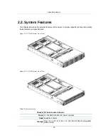
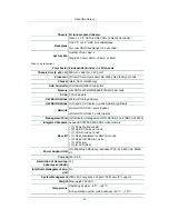
Chassis 2U rack-mounted chassis
Rear: 4 x 2.5” SATA 6Gb/s SSDs (2 pieces per node)
Backplane
One 3.5” or 2.5” HDD Front Backplane
Two rear HDD Backplanes (one per node)
System Fan
Number of fan cage: 4
Single Fan Size: 60mm x 60mm x 38mm
Table 2.2. Specifications
Form Factor 2 independent nodes in a 2U chassis
Chassis Size (L x W x H)
800 mm x 448 mm x 87.3 mm
Processor
(2) Intel® Xeon® processor E5-2600 v3/v4 family per node
Chipset
Intel® C612 (Wellsburg)
SAS Controller
LSI SAS HBA/RAID controller
Memory
(16) DDR4 1333/1600/1866/2100 MHz per node
PCI-E
2 PCIe x8 slots
SW RAID Options
Microsoft Storage Spaces
HW RAID Options
LSI Syncro CS Cluster-in-a-box Solution (optional)
Network
(2) Intel® 10G SFP+ ports (option)
(2) Intel® 10G Base-T ports (option)
Management Port
(1) Dedicated management 10/100BASE-T port (BMC AST2400)
Integrated Graphics
Aspeed AST2400 8 MB DDR3 video memory
Rear I/O
• (1) Power button w/LED
• (2) USB 3.0 ports per node
• (1) VGA D-sub per node
• (1) RJ45 (dedicated for BMC) per node
• (2) RJ45 10G BASE-T ports
• (1) COM port
• (1) ID LED (blue)
Power Support Unit
(2) 1400W high efficiency redundant PSU, 110-240 VAC 50/60
Hz
Current
12A~9.6A
Restriction of Hazardous
Substances (RoHS)
Yes
Intel Node Management Sup-
port
No
System Management
IPMI v2.0 Compliant, on board "KVM over IP" support
Weight
Maxi-weight: 33.3KG
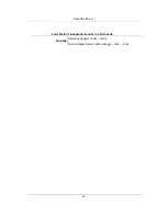
Temperature
Operating System: +5°C ~ +35°C
Non-operating System (with package): -40°C ~ +70°C
Содержание Demos R420 M2
Страница 1: ...Netberg Demos R420 M2 server User manual...
Страница 2: ...Netberg Demos R420 M2 server User manual...
Страница 12: ...1 Chapter 1 Safety Information...
Страница 19: ...8 Chapter 2 About the Server...
Страница 32: ...21 Chapter 3 Installing Hardware...
Страница 68: ...Installing Hardware 57 3 16 2 To install the strong plate Reverse the steps above to install the strong plate...
Страница 93: ...82 Chapter 4 Connectors...
Страница 95: ...Connectors 84 Figure 4 1 Mainboard Overview...
Страница 108: ...Connectors 97 4 9 Sensor Board Connectors Figure 4 13 Sensor Board 1 I2C Connector...
Страница 109: ...98 Chapter 5 Cable Routing...
Страница 110: ...Cable Routing 99 5 1 Cable Routing for 12 x 3 5 Hard Drives Configuration...
Страница 111: ...Cable Routing 100 5 2 Cable Routing for 24 x 2 5 Hard Drives Configuration...
Страница 112: ...101 Chapter 6 BIOS...
Страница 125: ...BIOS 114 6 3 1 5 CPU Advanced PM Tuning...
Страница 172: ...BIOS 161 6 4 2 View FRU Information...
Страница 176: ...BIOS 165 Menu Fields Settings Comments Network Device BBS Priorities 1...
Страница 182: ...171 Chapter 7 Rail Kit Assembly...
Страница 186: ...Rail Kit Assembly 175 Figure 7 3 Tightening the Thumbscrews...
Страница 187: ...176 Chapter 8 Troubleshooting...

