H3C UniServer R6900 G3, User Manual
The H3C UniServer R6900 G3 is a powerful server designed for high-performance computing. For detailed setup and usage instructions, download the free user manual from manualshive.com. This comprehensive manual provides essential information to optimize your server's performance and reliability. Access the manual now for a seamless user experience.
Share
Download


Reviews:
No comments
Related manuals for UniServer R6900 G3

eServer BladeCenter HS20Type 8832
Brand: IBM Pages: 158

UA-5231M
Brand: ICP DAS USA Pages: 4

xSeries 200VL
Brand: IBM Pages: 70

ProLiant ML110 Gen 10
Brand: HPE Pages: 5

SC10E4IG_L
Brand: San Telequip Pages: 49

t100
Brand: Atrust Pages: 21
HDR44
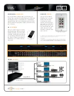
Brand: ATON Pages: 2

ABLELink SW2001
Brand: Atop Pages: 51

ABLELink GW21 MAXI Series
Brand: Atop Pages: 110

NPS 650
Brand: Axis Pages: 10

EXIP 414
Brand: Kathrein Pages: 20

H8DC8
Brand: Supermicro Pages: 78

SUPERO H8DGT-H
Brand: Supermicro Pages: 70

Supero H8DM3-2
Brand: Supermicro Pages: 78

H8DGU-LN4F+
Brand: Supermicro Pages: 82

SuperStorageSystem SSG-2028R-DN2R40L
Brand: Supermicro Pages: 84

Rackable C1110-RP6
Brand: Silicon Graphics Pages: 58

InfiniteStorage 3104
Brand: Silicon Graphics Pages: 64


