BIOS
148
Menu Fields
Settings
Comments
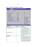
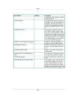
ror detection. They can be used as an
additional data bit.
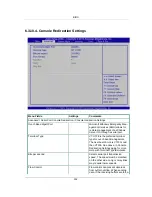
COM0 Stop Bits
Stop bits indicate the end of a serial
data packet. (A start bit indicates the
beginning). The standard setting is 1
stop bit. Communication with slow de-
vices may require more than 1 stop
bit
COM0 Flow Control
Flow control can prevent data loss
from buffer overflow. When sending
data, if the receiving buffers are full, a
stop
signal can be sent to stop the da-
ta flow. Once the buffers are empty, a
start
signal can be sent to re-start the
flow. Hardware flow control uses two
wires to send start/stop signals.
COM0 VT-UTF8 Combo Key Support
Enable VT-UTF8 Combination Key
Support for ANSI/VT100 terminals
COM0 Recorder Mode
With this mode enabled only text will
be sent. This is to capture Terminal
data
COM0 Resolution 100x31
Enables or disables extended termi-
nal resolution
COM0 Legacy OS Redirection Reso-
lution
On Legacy OS, the Number of Rows
and Columns supported redirection
COM0 Putty Keypad
Select FunctionKey and KeyPad on
Putty
COM0 Redirection After BIOS POST
The Settings specify if BootLoader is
selected than Legacy console redi-
rection is disabled before booting to
Legacy OS. Default value is Always
Enable which means Legacy console
Redirection is enabled for Legacy OS.
Содержание Demos R420 M2
Страница 1: ...Netberg Demos R420 M2 server User manual...
Страница 2: ...Netberg Demos R420 M2 server User manual...
Страница 12: ...1 Chapter 1 Safety Information...
Страница 19: ...8 Chapter 2 About the Server...
Страница 32: ...21 Chapter 3 Installing Hardware...
Страница 68: ...Installing Hardware 57 3 16 2 To install the strong plate Reverse the steps above to install the strong plate...
Страница 93: ...82 Chapter 4 Connectors...
Страница 95: ...Connectors 84 Figure 4 1 Mainboard Overview...
Страница 108: ...Connectors 97 4 9 Sensor Board Connectors Figure 4 13 Sensor Board 1 I2C Connector...
Страница 109: ...98 Chapter 5 Cable Routing...
Страница 110: ...Cable Routing 99 5 1 Cable Routing for 12 x 3 5 Hard Drives Configuration...
Страница 111: ...Cable Routing 100 5 2 Cable Routing for 24 x 2 5 Hard Drives Configuration...
Страница 112: ...101 Chapter 6 BIOS...
Страница 125: ...BIOS 114 6 3 1 5 CPU Advanced PM Tuning...
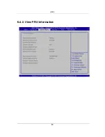
Страница 172: ...BIOS 161 6 4 2 View FRU Information...
Страница 176: ...BIOS 165 Menu Fields Settings Comments Network Device BBS Priorities 1...
Страница 182: ...171 Chapter 7 Rail Kit Assembly...
Страница 186: ...Rail Kit Assembly 175 Figure 7 3 Tightening the Thumbscrews...
Страница 187: ...176 Chapter 8 Troubleshooting...

