background image

SECTION IV. INSTALLATION STEPS

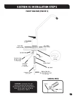
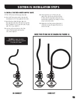
CORRECT

HOSE POSITIONS HOSE DIAGRAM (FIGURE 4)

10

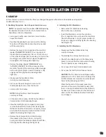
D.  INSTALL THE FEED WATER SUPPLY VALVE 


7.  

Shut off the water at the angle stop valve.

8.  

Use a 5/8" open-end wrench to loosen the  

compression nut on the angle stop riser tube.

9.  

Install the Feed Water Supply valve onto  

the angle stop. Use the 5/8" wrench to tighten  

the compression nut on the feed water supply  

valve. Do not over-tighten!

10.  

Reconnect the riser tube to the other  

end of the feed water supply valve.  

Do not over-tighten!

11.  

Fully insert the red 1/4" tube into the  

speed-fit connection and replace the red 

locking clip. The new feed water valve can  

be swiveled to position the tubing out of the 

way of under sink items.

12.  

Make sure the feed water supply valve is  

off before turning the angle stop valve on.  

Check for leaks

INCORRECT

CAUTION:

 A longer riser tube  

assembly will be required if a gentle  

loop cannot be made.

Содержание RO-4300Rx-DLX

Страница 1: ...The High Efficiency Reverse Osmosis Drinking Water System Installation Operation And Service Manual DLX...

Страница 2: ...ICROBIOLOGICALLY UNSAFE OR OF UNKNOWN QUALITY WITHOUT ADEQUATE DISINFECTION BEFORE OR AFTER THE SYSTEM Systems certified for cyst reduction may be used on disinfected water that may contain filterable...

Страница 3: ...or substances that contribute to tastes and odors IN LINE ACTIVATED CARBON POST FILTER The In Line Activated Carbon Post Filter is located after the Holding Tank and has been designed to reduce the ta...

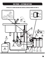
Страница 4: ...ct 3 8 Blue 6 7 8 Polytube Tee Stage 3 Carbon Post Filter Housing Stage 2 Reverse Osmosis Membrane Housing Stage 1 Sediment Carbon Pre Filter Housing Locate Drain Clamp Above P Trap Feed Water Valve C...

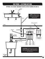
Страница 5: ...this manual Cover RO Manifold Drinking Water Holding Tank Mount Holding Tank On Shelf Or Strap Between Floor Joists Shelf or straps not included Stage 3 Activated Carbon Post Filter Housing Stage 2 Re...

Страница 6: ...ble to the user as reverse osmosis treated water when the system is operated without a storage tank or when the storage tank is bypassed Efficiency rating means the percentage of the influent water to...

Страница 7: ...ws or machine screws and nuts for mounting the manifold or concrete anchors for hanging on basement wall Additional tubing or tube connectors Plastic wire ties for organizing tubing B TOOLS RECOMMENDE...

Страница 8: ...as it will extend the life of the R O Membrane 3 R O Manifold Assembly The manifold can be installed on either the right or left side of the under sink area or a cabinet The right side is recommended...

Страница 9: ...sher Rubber Connector Faucet 3 8 x 7 16 Drain Line From Air Gap To Drain 3 8 Black Tubing Drain Line To Air Gap 1 4 Black Tubing AIR GAP ONLY GRINDING WHEEL Sink Top Metal Porcelain CAUTION Be careful...

Страница 10: ...Punch 5 Set the punch and turn the nut with a wrench to cut the hole D PREPARE THE R O AIR GAP FAUCET ASSEMBLY FOR INSTALLATION 1 Using the diagram in Figure 3 assemble the Air Gap Spigot with all th...

Страница 11: ...ion nut on the feed water supply valve Do not over tighten 10 Reconnect the riser tube to the other end of the feed water supply valve Do not over tighten 11 Fully insert the red 1 4 tube into the spe...

Страница 12: ...Faucet Route the tubing to the Drain Clamp and trim to length NOTE When cutting the polytubing make clean square cuts failing to do so could result in poor connections and possible leaks CAUTION The...

Страница 13: ...hen press firmly again to insure proper seating 19 Locate the White tubing Remove the yellow plug from the fitting labeled Out on the manifold and insert the tubing 20 Locate the 3 8 Blue Product Wate...

Страница 14: ...OSE the Feed Water Valve and open the Dispensing Faucet Allow the Holding Tank to completely drain then remove the Sediment Carbon Filter Housing the farthest of the three from the In Out ports empty...

Страница 15: ...ion it is better to empty the Holding Tank and allow the system to produce fresh water for use If the system is not used for 3 4 weeks or longer it is a good idea to re sanitize the system and to chan...

Страница 16: ...the Faucet in the following order close the Faucet and open the Holding Tank Valve When the Faucet is first opened expect air and carbon fines very fine black powder from the new Post Filter to be ri...

Страница 17: ...tem A The Permeate pump brine side should be installed between the R O System and the air gap faucet connection From the R O plug black tube into BRINE IN port B Connect a new length long enough to re...

Страница 18: ...ASO Valve is malfunctioning In Line Activated Carbon Post Filter is plugged LOW PRESSURE AT THE DISPENSING FAUCET In Line Activated Carbon Post Filter is plugged Replace Post Filter Air precharge in t...

Страница 19: ...gases in the Feed Water Pretreat Feed Water to remove dissolved gases Increase in Product Water TDS See high TDS in the Product Water section AMBER LIGHT ON WATER QUALITY MONITOR System not being used...

Страница 20: ...EXPLODED VIEW AND PARTS LIST 19A Water Quality Test Kit 23 Nitrate Nitrite Test Kit Optional Deluxe Components 17 19 20 14 13 12 11 16 18 10 9 15 1 2 3 4 5 6 7 8 24 25 19...

Страница 21: ...O Membrane 50 gpd 189 lpd Part No CLK TF 50 13 Housing O Ring 14 Housing 15 Water Quality Monitor Board w Probes 16 Drain Restrictor 50 GPD 189 lpd Green 17 Cover 18 Activated Carbon Post Filter Part...

Страница 22: ...t and carbon filters whose service life depends on feed water conditions In addition the membrane is only warranted if the required feed water conditions are met The above warranty will also not apply...

Отзывы: