background image

620 County Road 4841, Haslet, TX 76052 

Ph 817.439.1108    Fax 817.439.0633 

www.machine-technologies.com 


MP-25 User Manual 


60010120   

ASSY, MP 25-SO - SINGLE PHASE 220V 

 
60010121   

ASSY, MP 25-HO - 3 PHASE - 220V 

 
60010122   

ASSY, MP 25-SO - 3 PHASE - 220V 


Revision - – 10/03/2008

Содержание MP-25

Страница 1: ...et TX 76052 Ph 817 439 1108 Fax 817 439 0633 www machine technologies com MP 25 User Manual 60010120 ASSY MP 25 SO SINGLE PHASE 220V 60010121 ASSY MP 25 HO 3 PHASE 220V 60010122 ASSY MP 25 SO 3 PHASE...

Страница 2: ...efore starting this machine please complete the following Machine Date of purchase Machine serial number Please read the following information contained within this manual and fully familiarize yourse...

Страница 3: ...ASSY WATER CONTROL MP 25 7GPM 15 Motor mount 16 60010134 ASSY UPPER MTR MNT MP 25 16 Mixing shaft complete and clean out shaft complete 17 60010125 ASSY DRIVE MIX SHAFT MP 25 17 60010126 ASSY SHAFT CL...

Страница 4: ...teners are present and correctly fitted before attempting to start or operate the machine Ensure that the pump unit is correctly fastened to the front of the hopper unit of the machine and free of dam...

Страница 5: ...gressive cavity pump unit comprising of a helical rotating rotor with the rubber lined stator As the rotor rotates material is drawn fed into open rubber cavities which then transform into pockets The...

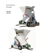
Страница 6: ...Page 6 Machine illustrations Photographs Single phase STD output unit shown...

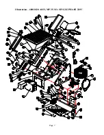
Страница 7: ...Page 7 Illustration 60010120 ASSY MP 25 SO SINGLE PHASE 220V...

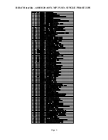
Страница 8: ...Page 8 Bill of Materials 60010120 ASSY MP 25 SO SINGLE PHASE 220V...

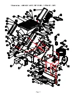
Страница 9: ...Page 9 Illustration 60010121 ASSY MP 25 HO 3 PHASE 220V...

Страница 10: ...Page 10 Bill of Materials 60010121 ASSY MP 25 HO 3 PHASE 220V...

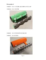
Страница 11: ...Page 11 Photographs of 30000039 D8 1 5 STATOR ADJ GREEN INTCLAMP 30000040 D8 1 5 ROTOR 30000041 D6 3 STATOR FIXED ORANGE 30000042 D6 3 ROTOR...

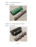
Страница 12: ...Page 12 30000043 D4 3 STATOR FIXED GREEN 30000044 D4 3 ROTOR 30000045 R8 1 5 STATOR ADJ BLACK INTCLAMP 30000046 R8 1 5 ROTOR...

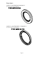
Страница 13: ...Page 13 Pump adapters 44010257 ADAPTER PUMP 90MM MP 25 to suit D series rotors and stators 44010258 ADAPTER PUMP 113 5MM MP 25 to suit R series rotors and stators...

Страница 14: ...Page 14 Water plate assemblies 60010136 ASSY WATER CONTROL MP 25 4GPM...

Страница 15: ...Page 15 60010142 ASSY WATER CONTROL MP 25 7GPM...

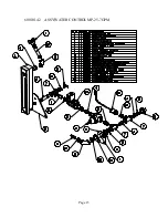
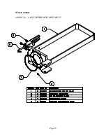
Страница 16: ...Page 16 Motor mount 60010134 ASSY UPPER MTR MNT MP 25...

Страница 17: ...Page 17 Mixing shaft complete and clean out shaft complete 60010125 ASSY DRIVE MIX SHAFT MP 25...

Страница 18: ...Page 18 60010126 ASSY SHAFT CLEAN OUT MP 25...

Страница 19: ...Page 19 Water pressure tester water hoses and fan duct 60010140 TESTER WATER PRESS 35MM MALE 600PSI 60010139 ASSYWATER HOSE COMPLETE MP 25...

Страница 20: ...Page 20 60010147 ASSY PUMP HOSE COMPLETE MP 25...

Страница 21: ...Page 21 60010144 ASSY FAN DUCT MP 25 60010148 ASSY WASHDOWN HOSE COMPLETE MP 25...

Страница 22: ...Page 22 Electric Drive unit Typical layout Shown in cutaway view of upper motor mount Unit must be greased on a daily job by job basis...

Страница 23: ...Page 23 Cutaway view of seal dowel adapter and shaft arrangement Showing relationship between grooves in adaptor and seal to allow grease to flow...

Страница 24: ...equent clean down the module must be disconnected from the electrical supply opened and the inside inspected for debris and or water ingress ALL water and debris must be removed immediately using wipe...

Страница 25: ...e is equipped with a water pump used as a booster pump to help ensure consistent water pressure and as such the unit will not run unless the water pressure switch is closed For maintenance the water p...

Страница 26: ...Page 26 Illustrations 20000046 3 phase...

Страница 27: ...Page 27 20000047 single phase...

Страница 28: ...Page 28 With cowl...

Страница 29: ...wheels at the front The machine can be picked up using a forklift by simply inserting the forks under the base from the rear and ensuring that they are close enough together to prevent damage to the...

Страница 30: ...hus prone to damage from impact with objects in front of the machine or from the ground itself The machine must be eased up curbs or steps Once the machine has been positioned then the locks on the re...

Страница 31: ...e all items from the hopper excluding the mixing shaft but including the pressure tester the power cord and socket assembly the Quality check sheet and user manual and the wired remote Check that the...

Страница 32: ...ssembly Ensure that the drive shaft is fully engaged in the rotor at the pumping end of the machine It is essential that the round center guide be in the pilot hole of the rotor and that the lower spa...

Страница 33: ...Page 33 Rotate the motor output shaft and auger drive by hand or a suitable lever until the flat end of the mixing shaft aligns with the slot in the end of the hauling bracket on the motor...

Страница 34: ...s been running the compressive force will be reduced or eliminated to within working limits During pumping the compression will be present during reverse the compression will be relieved If full closu...

Страница 35: ...from the bus bars to ensure that no voltage exists on the cables 4 Make the connection between the power cord and the main distribution box using the supplied electric cord with plug and your power s...

Страница 36: ...plug can be removed and be used as a level Once water flow from the lower port the prime button should be released and the port plug replaced 10 Press the START button and observe the machine to turn...

Страница 37: ...direction and observe fluid to be displaced from the pump through the pressure tester 6 Increase the speed of the machine to your chosen setting and slowly close the valve on the pressure tester and o...

Страница 38: ...ish soap running through the machine 5 Measure the flow of output at the discharge point 6 Progressively and evenly tighten the clamp on the stator until no more output is achieved 7 Stop the machine...

Страница 39: ...with clean water Do not spray water on or in control box Control box should be wiped down with a damp rag Remove the mixing shaft and clean off ALL material If access is required in to the hopper disc...

Страница 40: ...t the rear of the machine DO NOT spray water inside the fan shroud or direct the jet towards the shroud or water can get into the drive module and damage electrical parts Prior each clean down the dri...

Страница 41: ...out fully cured and hardened material 5 The clean out shaft is to be turned at the lowest speed with plenty of running water as any debris created will be passed through the stator and the water will...

Страница 42: ...ppropriate lubrication The lubricant produces sliding friction between the rotor and the stator If this lubricating film is damaged high temperatures are reached and the elastomer wears within a very...

Страница 43: ...nsportation charges unless specifically identified and authorized in writing by Machine Technologies Nor does the warranty apply to any unit upon which repairs or unauthorized alterations have been ma...

Отзывы: