Audible Alarm Settings and Service Functions
N-550
33
default values that have been stored. Factory-set power-on default values are
listed in Table 4 on page 38.
Accessing Menu Items
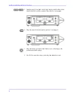
1. Menu items can be accessed at any time by pressing the SpO
2
Alarm
Limit and Pulse Rate Alarm Limit buttons simultaneously until the
option 1 screen is displayed.
2. Press the Adjust Up or Adjust Down button to select the menu item
number. Menu items 4, 5, 6, 7, 8, 11, 12, 13, and 14 have sub-options
within them that can be selected by first pressing the
SatSeconds
Alarm
Limit button, and then pressing the Adjust Up or Adjust Down button.
The sub-option being selected is displayed in the %SpO
2
display window.
Note
:
Service menu items numbered above 5 cannot be accessed if a sensor
is connected to the N-550.
3. Once adjustments have been made within a menu item, the
SatSeconds
Alarm Limit button can be used to initiate the current selection. To save
the current settings as power-on default values, refer to the procedure
outlined in
Menu Item 9 (Save Current Values as Power-On Defaults)
Note
:
If a period of 10 seconds passes with no button presses, the N-550
exits the menu item selected and return to normal monitoring, and no
changes will are made.
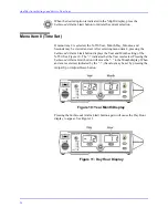
Menu Item 1 (Trend Print)
Trend data can be viewed (if connected to a PC), or a trend printout can be
made, if the
SatSeconds
Alarm Limit button is pressed when menu item 1 is
displayed. For more information about trend printouts, refer to the N-550
Operator’s manual.
Содержание OxiMax N-550
Страница 1: ...N 550 Pulse Oximeter Service Manual min min SpO2 N 550 SatSeconds SpO2 ...
Страница 10: ...Blank Page ...
Страница 38: ...Blank Page ...
Страница 64: ...Blank Page ...
Страница 81: ...Disassembly Guide N 550 71 Figure 39 Equipotential Ground Terminal Removed ...
Страница 82: ...Blank Page ...
Страница 86: ...Spare Parts 76 Figure 40 Exploded View ...
Страница 90: ...Blank Page ...
Страница 108: ...Blank Page ...
Страница 120: ...Blank Page ...
Страница 130: ...Figure 56 Main PCB Parts Locator Diagram 129 Technical Description N 550 ...
Страница 131: ...Figure 57 Front Panel Parts Locator Diagram 131 N 550 Technical Description ...
Страница 136: ...Blank Page ...
Страница 137: ... ...

