


Upgrading Your System 4-45
Figure 4-47. Connecting the Power and Data Cables
10.
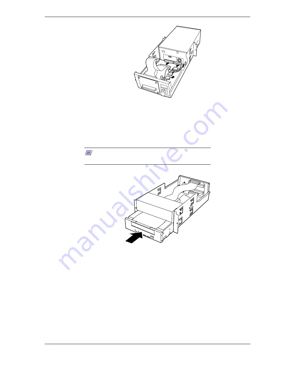
Push the device all the way into the media bay until its screw holes are
aligned directly in front of the screw holes on both sides of the 5 1/4-inch
device tray, see Figure 4-48. Then using the screws supplied with the device
secure it to the 5 1/4-inch device tray.
Note:
Do not use the screws used to secure the blank
panel to the 5 1/4-inch device tray.
Figure 4-48. Installing the Device into the 5 1/4-inch Device Tray
11.
Insert the 5 1/4-inch Device Tray into the BSU chassis until it is firmly
seated into its board connector.
12.
Secure the 5 1/4-inch Device Tray to the front of the BSU chassis with the
two screws removed in step 5 above, see Figure 4-49.
Содержание Express5800/180Ra-7
Страница 1: ... U s e r s G u i d e EXPRESS5800 180Ra 7 ...
Страница 2: ...xxx ...
Страница 3: ... U s e r s G u i d e EXPRESS5800 180Ra 7 ...
Страница 10: ...viii Contents ...
Страница 94: ...3 28 Configuring Your System ...
Страница 134: ...4 40 Upgrading Your System A B C Figure 4 43 Recabling the SCSI Interface Cable ...
Страница 166: ...4 72 Upgrading Your System ...
Страница 206: ...5 40 Problem Solving ...
Страница 207: ...A Specifications Basic System Unit BSU Disk Expansion Unit DEU ...
Страница 212: ...A 6 Specifications ...
Страница 218: ...B 6 Interrupt Request PCI IRQ Device I O Port Address Assignments ...
Страница 229: ...D ROMPilot BIOS Error Codes ROMPilot BIOS Error Codes ...
Страница 232: ...D 4 ROMPilot BIOS Error Codes ...
Страница 242: ...10 Glossary ...
Страница 246: ...4 Equipment Log ...
Страница 250: ...Index 4 ...
Страница 251: ...xx ...
Страница 252: ... 456 01516 000 ...


