


4-18
Upgrading Your System
16.
Check that the processor is firmly seated in the bottom of the socket and
reattach the CPU cover removed in step 5 above.
Note:
If the processor is not inserted correctly, the
Status LED lights amber and the error message "CPU
Missing" appears on the LCD when the power cord is
connected.
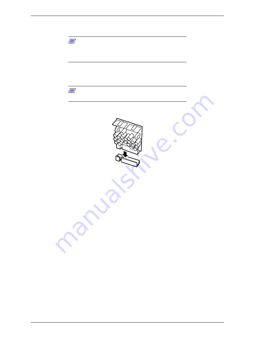
17.
Install the VRM, as shown in Figure 4-14. Each processor has a VRM
associated with it.
Note:
As processors are added you need to install
additional VRMs.
Figure 4-14. Installing a VRM
18.
Reattach the BSU top cover. See
Installing the Top Cover
in subsection
Installing/Removing the BSU Front Bezel and Top Cover
earlier in this
chapter.
19.
Reinstall the two fan modules previously removed. See
Installing the Front
and Rear Fan Modules
earlier in this chapter.
20.
If tower-based system, reattach the top cover of the tower cabinet. See
Installing the Top Cover of the Tower Cabinet
earlier in this chapter.
Содержание Express5800/180Ra-7
Страница 1: ... U s e r s G u i d e EXPRESS5800 180Ra 7 ...
Страница 2: ...xxx ...
Страница 3: ... U s e r s G u i d e EXPRESS5800 180Ra 7 ...
Страница 10: ...viii Contents ...
Страница 94: ...3 28 Configuring Your System ...
Страница 134: ...4 40 Upgrading Your System A B C Figure 4 43 Recabling the SCSI Interface Cable ...
Страница 166: ...4 72 Upgrading Your System ...
Страница 206: ...5 40 Problem Solving ...
Страница 207: ...A Specifications Basic System Unit BSU Disk Expansion Unit DEU ...
Страница 212: ...A 6 Specifications ...
Страница 218: ...B 6 Interrupt Request PCI IRQ Device I O Port Address Assignments ...
Страница 229: ...D ROMPilot BIOS Error Codes ROMPilot BIOS Error Codes ...
Страница 232: ...D 4 ROMPilot BIOS Error Codes ...
Страница 242: ...10 Glossary ...
Страница 246: ...4 Equipment Log ...
Страница 250: ...Index 4 ...
Страница 251: ...xx ...
Страница 252: ... 456 01516 000 ...


