


4-44
Upgrading Your System
6.
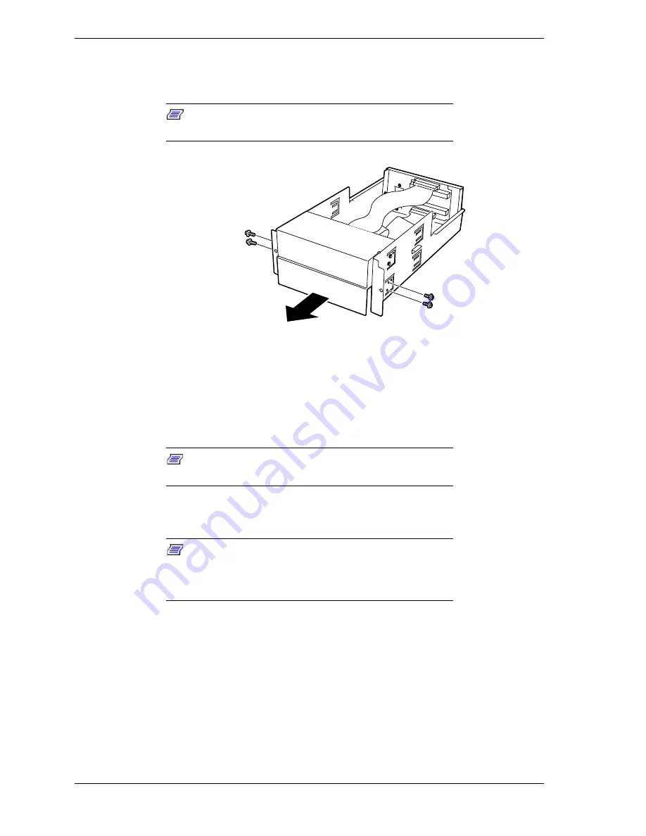
Each empty media bay has a blank panel. From the bay where you want to
install a drive, remove the four screws securing the blank panel to the
5 1/4-inch device tray and remove the blank panel, see Figure 4-46.
Note:
When installing a full height 5 1/4-inch device,
remove two blank panels.
Figure 4-46. Removing the Blank Panel
7.
Remove the device from its protective wrapper and place it on an antistatic
surface. Record the drive model and serial number in the equipment log.
8.
Set any device jumpers or switches on the device. Refer to the installation
procedures that come with the device.
Note:
All 5 1/4-inch devices must have terminators
removed.
9.
Insert the device halfway into the media bay and connect the power and data
cables to the device, see Figure 4-47.
Note:
If a power supply branch cable or relay cable is
provided with the device, make sure you use that cable.
Refer to the installation procedures that come with the
device.
Содержание Express5800/180Ra-7
Страница 1: ... U s e r s G u i d e EXPRESS5800 180Ra 7 ...
Страница 2: ...xxx ...
Страница 3: ... U s e r s G u i d e EXPRESS5800 180Ra 7 ...
Страница 10: ...viii Contents ...
Страница 94: ...3 28 Configuring Your System ...
Страница 134: ...4 40 Upgrading Your System A B C Figure 4 43 Recabling the SCSI Interface Cable ...
Страница 166: ...4 72 Upgrading Your System ...
Страница 206: ...5 40 Problem Solving ...
Страница 207: ...A Specifications Basic System Unit BSU Disk Expansion Unit DEU ...
Страница 212: ...A 6 Specifications ...
Страница 218: ...B 6 Interrupt Request PCI IRQ Device I O Port Address Assignments ...
Страница 229: ...D ROMPilot BIOS Error Codes ROMPilot BIOS Error Codes ...
Страница 232: ...D 4 ROMPilot BIOS Error Codes ...
Страница 242: ...10 Glossary ...
Страница 246: ...4 Equipment Log ...
Страница 250: ...Index 4 ...
Страница 251: ...xx ...
Страница 252: ... 456 01516 000 ...


