


Upgrading Your System 4-57
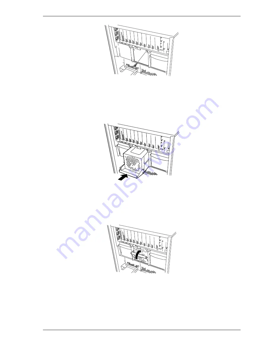
Figure 4-61. Removing the BSU Power Supply Bay Blank Cover
5.
Pull down the front lever of the new power supply to be installed.
6.
Slide the power supply into the bay, see Figure 4-62.
Figure 4-62. Installing the New Power supply
7.
Secure the power supply by lifting its front lever and then pushing it firmly
into the bay until you hear it click, see Figure 4-63.
Figure 4-63. Securing the New Power supply
8.
Plug one end of the power cords into the AC input receptacles on the rear of
the BSU and connect the other end into the AC wall outlets. While AC
power is being connected the "PWR" LED on the power supplies flash
indicating that AC power is being applied to them.
Содержание Express5800/180Ra-7
Страница 1: ... U s e r s G u i d e EXPRESS5800 180Ra 7 ...
Страница 2: ...xxx ...
Страница 3: ... U s e r s G u i d e EXPRESS5800 180Ra 7 ...
Страница 10: ...viii Contents ...
Страница 94: ...3 28 Configuring Your System ...
Страница 134: ...4 40 Upgrading Your System A B C Figure 4 43 Recabling the SCSI Interface Cable ...
Страница 166: ...4 72 Upgrading Your System ...
Страница 206: ...5 40 Problem Solving ...
Страница 207: ...A Specifications Basic System Unit BSU Disk Expansion Unit DEU ...
Страница 212: ...A 6 Specifications ...
Страница 218: ...B 6 Interrupt Request PCI IRQ Device I O Port Address Assignments ...
Страница 229: ...D ROMPilot BIOS Error Codes ROMPilot BIOS Error Codes ...
Страница 232: ...D 4 ROMPilot BIOS Error Codes ...
Страница 242: ...10 Glossary ...
Страница 246: ...4 Equipment Log ...
Страница 250: ...Index 4 ...
Страница 251: ...xx ...
Страница 252: ... 456 01516 000 ...


