

5.1 Installing a 3.5-inch HDD into the tray
5.1.1 Removing the HDD tray
IMPORTANT!
ALWAYS use the top hard drive slot when installing a hard drive into the system.
5. Installing the hard drives
© by Infortrend Technology, Inc. All rights reserved.
EonServ 7000 Series
Quick Installation Guide
Rear rack posts
M5 x 9.0mm
Z M0 0 0 1 1 0 G A Q 0 6 2 1 4
3U, M5 cage nut position
Front rack posts
Unit boundary
Unit boundary
2U, M5 cage nut position
11
WARNING!
Ÿ
Only qualified service personnel should install and service this product to avoid injury.
Ÿ
Observe all ESD procedures during installation to avoid damaging the equipment.
1. Preparing the tools
Unpack the equipment and ensure that the following tools are available before installation.
1.1 User-provided tools
Ÿ
Phillips screwdriver (medium size)
Ÿ
Flat blade screwdriver (small size)
Ÿ
Anti-static wrist wrap
Ÿ
Host link cables
1.2 Accessory box contents
Ÿ
Screws: M5, M6, No. 10-32, No. 5-32
Ÿ
Cables: Power cord x 2
NOTE:
Refer to the
Unpacking List
for the exact number of items bundled in the package.
2. Installing the rackmount
WARNING!
Due to the weight of the enclosure and installation procedure requirements, DO NOT install the
HDDs to the enclosure when assembling with the rackmount. At least one personnel should assist
you with the installation.
2.1 Slide rail kit
2.1.1 Checking the contents of the slide rail kit
1
2
3
2 x inner glides
4
6 x Flathead screws
No. 6-32 L4
5
10 x Truss head
screws M5 x 9.0 mm
6
4 x M5 cage nuts
7
4 x 25 mm M5 screws
8
4 x25 mm M6 screws
9
4 x 25.4 mm
No. 10-32 screws
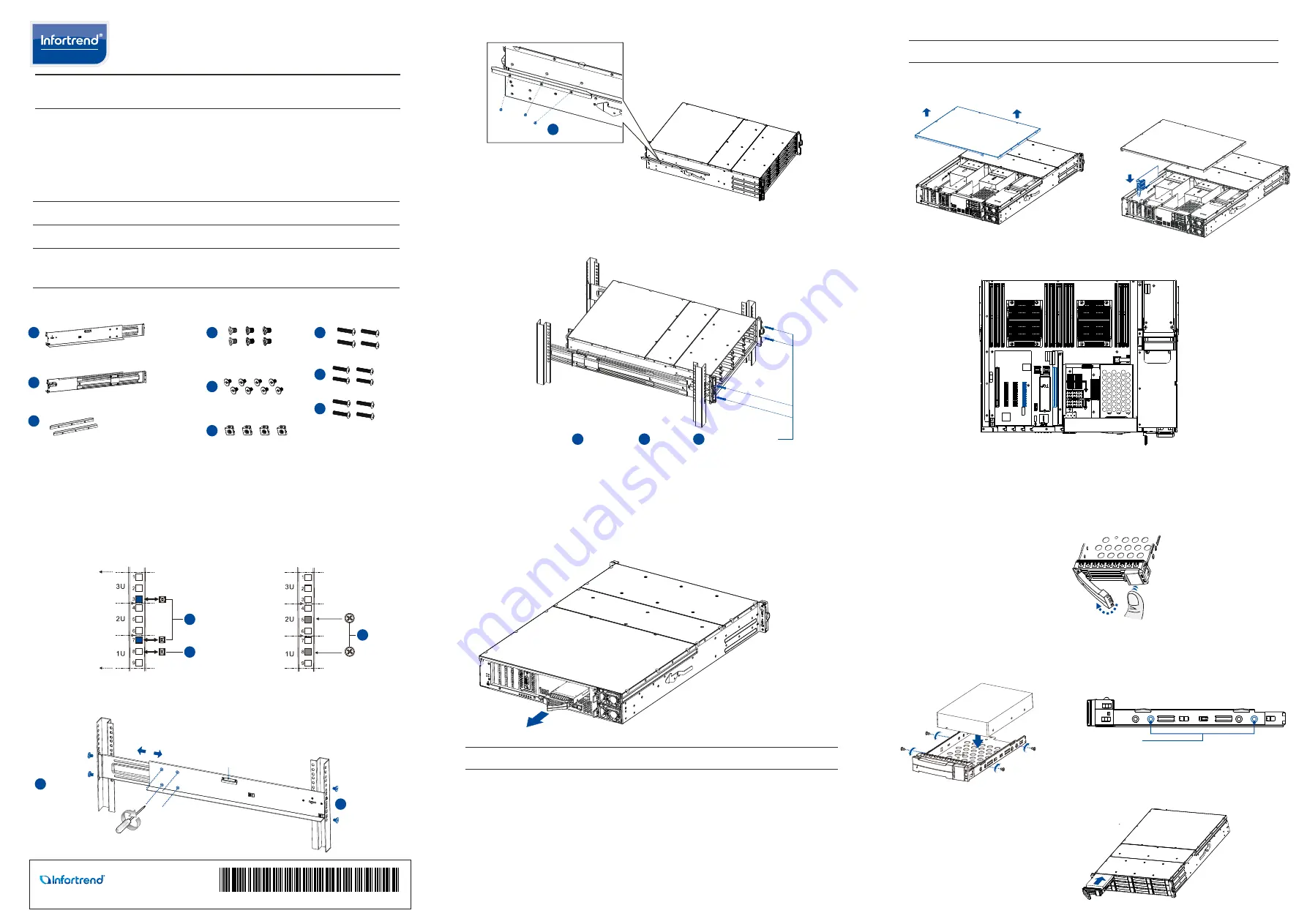
2.1.2 Installing the slide rail kit
1. Determine the position where the enclosure will be installed to the front and rear rack
posts and insert the cage nuts into the designated holes of the front rack post.
Positions for chassis/M5 cage nut:
4. With the assistance of another person, lift and insert the enclosure onto the slide rail.
Ensure that the inner glides on both sides of the enclosure meet the inner glide rail.
Secure the enclosure using the M5, M6, or No. 10-32 screws from the front.
2.
Loosen the four screws on the slide rail then adjust its length. After the length
adjustment, secure the slide rails to the front and rear posts with the truss head screws.
4
No. 6-32
3.
Attach the inner glides to both sides of the enclosure using flathead screws No. 6-32.
3. Installing the system drive
There are two 2.5-inch system drive slots near the IO panel. If you purchased the system
with the hard drive(s), they should have been assembled together. If not, you must install
them manually with the following instructions:
1. Gently pull out the drive tray from the enclosure.
2. Install the hard drive into the tray and insert it back to the enclosure.
4. Installing a PCIe card (optional)
NOTE:
Confirm with the support personnel about PCIe card qualification before purchase/installation.
1.
Loosen the screws and remove the
cover.
2.
Install t he PCIe card into the PCIe slot,
then place back the cover and secure it
with the screws.
For on-CPU models (71XX models), you can ONLY use two specific PCIe slots. See the
marked blue slots in the illustration below.
Press the release button to open
the bezel and gently pull the HDD
tray from the enclosure.
5.1.2 Attaching HDD tray
1. Orient the HDD to the tray with the
interface connectors facing the open
side of the tray and the label is facing up.
2. Secure the drive by fastening the four (4)
of the bundled screws.
3.5-inch SATA
HDD holes
5.1.3 Inserting and securing the HDD tray
Insert the assembled HDD and HDD tray to
the enclosure with the tray bezel open.
1 x Mounting bracket assembly, left side
1 x Mounting bracket assembly, right side
4
M5 x 9.0mm
Inner glide rail
M5 x 9.0mm
5
5
6
6
25 mm M5 or
25 mm M6
7
8
25.4 mm No. 10-32
9


