APPENDIX A PROGRAM LIST
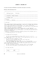
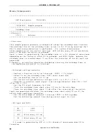
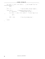
PU4 = 0b00001000;
/* Connect on-chip pull-up resistor to P43
*/
PM4 = 0b00001000;
/* Set P43 as input mode, P40-P42 and P44-
P47 as output mode */
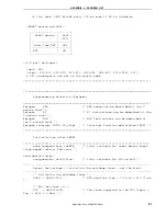
/*----------------------------------------------------------------------------
Initialize the port 12
----------------------------------------------------------------------------*/
P12 = 0b00000000;
/* Set output latches of P120-P123 as low
*/
PM12 = 0b11110000;
/* Set P120-P123 as output mode */
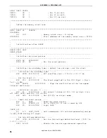
/*----------------------------------------------------------------------------
Initialize the port 13
----------------------------------------------------------------------------*/
P13 = 0b00000001;
/* Set output latch of P130 as high */
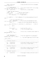
/*----------------------------------------------------------------------------
Set the interrupt
----------------------------------------------------------------------------*/
INTM0 = 0b00000000;
/* Set the valid edge of INTP1 to falling
edge */
PIF1 = 0;
/* Clear invalid interrupt requests in
advance */
PMK1 = 0;
/* Release the INTP1 interrupt mask */
return;
}
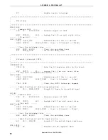
/*****************************************************************************
Main
loop
*****************************************************************************/
void main(void){
unsigned int unCnt120ms;
/* 16-bit variable for 120 ms wait */
EI();
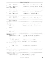
/*
Enable
vector
interrupt
*/
while
(1){
P2 ^= 0b00000001;
/* Reverse output of LED1 */
for (unCnt120ms = 0; unCnt120ms < 6666; unC+){
/*
Wait of about 120 ms */
NOP();
}
WDTE = 0xAC;
/* Clear the watchdog timer */
}
}
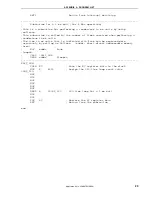
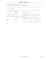
/*****************************************************************************
External interrupt INTP1
*****************************************************************************/
__interrupt void fn_intp1(){
unsigned int unCnt;
/* 16-bit variable for a wait */
Application Note U18847EJ1V0AN
33

