CHAPTER 1 OVERVIEW
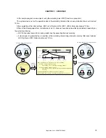
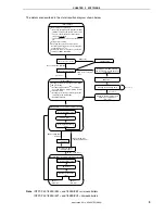
In this sample program, an example of using the watchdog timer (WDT) function is presented.
The system clock is set as the operation clock of the watchdog timer and the runaway detection time is set to about
131 ms.
After completion of the initial settings, LED1 out of the two LEDs (LED1, LED2) blinks about every 120 ms.
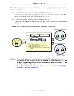
Either of the following operations is performed at a 50% chance of occurrence (see the figure below), depending on
the switch input timing.
•
LED1 blinks about every 60 ms during switch input by executing interrupt servicing.
•
A reset signal is generated by an overflow of the watchdog timer during interrupt servicing. After reset release,
LED2 lights and LED1 blinks about every 120 ms.
SW
On (turned on for at least 10 ms)
<Input>
LED2
LED1
<Output>
Blinks about
every 120 ms.
Lights.
LED2
LED1
<Output>
Blinks about
every 60 ms.
<1>
<2>
<During interrupt servicing execution>
<After WDT reset generation>
Main processing
Interrupt
servicing
WDT clear
WDT clear
WDT clear
WDT clear
WDT clear
WDT clear
About 120 ms
X ms
About
10 ms
(Chattering
removal)
About 60 ms
About 60 ms
Switch: on
Switch: off
<1> X ms + 10 ms + 60 ms
≤
131 ms
→
No overflow occurs.
→
Interrupt servicing continues.
WDT overflow time = 2
20
/f
X
= About 131 ms (f
X
= 8 MHz)
<2> X ms + 10 ms + 60 ms > 131 ms
→
An overflow occurs.
→
A WDT reset is generated during interrupt
servicing.
The probability that an overflow occurs is 61 ms/120 ms,
which is about 50%, because an overflow occurs when X ms > 61 ms.
LED2
LED1
<Output>
Blinks about
every 120 ms.
<During main loop execution>
Interrupt
servicing
starts
About 120 ms
• • •
Application Note U18847EJ1V0AN
3

