APPENDIX A PROGRAM LIST
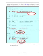
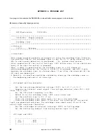
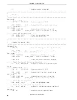
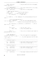
MOV
A,
#40
; Assign the 200 us wait count value
;----- 200 us wait -----
WAIT_200US:
DEC
A
BNZ
$WAIT_200US
; 0.5[us/clk] x 10[clk] x 40[count] = 200[us]
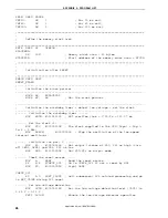
;----- Wait for VDD >= VLVI -----
WAIT_LVI:
MOV
WDTE, #0ACH
; Clear the watchdog timer
BT
LVIF, $WAIT_LVI
; Branch if VDD < VLVI
SET1 LVIMD
; Set so that an internal reset signal is
generated when VDD < VLVI
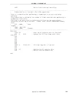
;----- Set the clock <2> -----
SET_CLOCK:
MOV
PPCC, #00000001B ; The clock supplied to the peripheral hardware
(fxp) = fx/2 (= 4 MHz)
; -> The clock supplied to the CPU (fcpu) = fxp
= 4 MHz
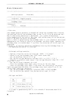
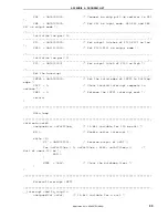
;-----------------------------------------------------------------------------
;
Initialize the port 0
;-----------------------------------------------------------------------------
MOV
P0,
#00000000B ; Set output latches of P00-P03 as low
MOV
PM0, #11110000B ; Set P00-P03 as output mode
;-----------------------------------------------------------------------------
;
Initialize the port 3
;-----------------------------------------------------------------------------
MOV
P3,
#00000000B ; Set output latches of P30-P33 as low
MOV
PM3, #11110000B ; Set P30-P33 as output mode
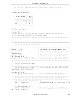
;-----------------------------------------------------------------------------
;
Initialize the port 4
;-----------------------------------------------------------------------------
MOV
P4,
#00000000B ; Set output latches of P40-P47 as low
MOV
PU4, #00001000B ; Connect on-chip pull-up resistor to P43
MOV
PM4, #00001000B ; Set P43 as input mode, P40-P42 and P44-P47 as
output mode
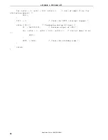
;-----------------------------------------------------------------------------
;
Initialize the port 12
;-----------------------------------------------------------------------------
MOV
P12, #00000000B ; Set output latches of P120-P123 as low
MOV
PM12, #11110000B ; Set P120-P123 as output mode
;-----------------------------------------------------------------------------
;
Initialize the port 13
;-----------------------------------------------------------------------------
MOV
P13, #00000001B ; Set output latch of P130 as high
;-----------------------------------------------------------------------------
;
Set the interrupt
;-----------------------------------------------------------------------------
MOV
INTM0,
#00000000B ; Set the valid edge of INTP1 to falling
edge
CLR1 PIF1
; Clear invalid interrupt requests in advance
CLR1 PMK1
; Release the INTP1 interrupt mask
Application Note U18847EJ1V0AN
27

