CHAPTER 4 SETTING METHODS
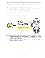
(1) Setting the operation clock of the watchdog timer and overflow time
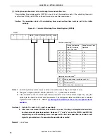
The watchdog timer mode register (WDTM) is used to set the operation clock of the watchdog timer and
overflow time. Writing to WDTM can be performed only once after reset release.
Caution The operation clock of the watchdog timer and overflow time must be set in the initial
settings.
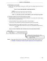
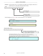
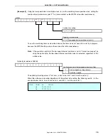
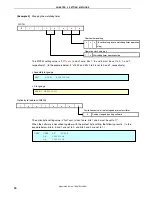
Figure 4-1. Format of Watchdog Timer Mode Register (WDTM)
WDTM
Notes 1.
If watchdog timer operation stop is selected, the overflow time setting is invalid (don’t care).
2.
The cycle is longest (WDCS2, WDCS1, WDCS0 = 1, 1, 1) when reset is released.
3.
If the oscillation control of the low-speed internal oscillator is set to “Cannot be stopped” by using the
option byte, the operation clock cannot be selected. The low-speed internal oscillation clock is selected
regardless of the written value. Refer to
(3) Setting the oscillation control of the low-speed internal
Cautions 1. Set bits 7, 6, and 5 to 0, 1, and 1, respectively.
2. After reset is released, WDTM can be written only once. If writing is attempted a second time,
an internal reset signal is generated. However, if “1” and “x” are set for WDCS4 and WDCS3,
respectively, and the watchdog timer is stopped at the first write operation, no internal reset
signal is generated even if a second write operation is executed.
Remark
x: don’t care
0 1 1
WDCS
4
WDCS
3
WDCS
2
WDCS
1
WDCS
0
Overflow time setting
Notes 1, 2
During Low-Speed
Internal Oscillation
Clock Operation
During System Clock
Operation
0 0 0 2
11
/f
RL
2
13
/f
X
0 0 1 2
12
/f
RL
2
14
/f
X
0 1 0 2
13
/f
RL
2
15
/f
X
0 1 1 2
14
/f
RL
2
16
/f
X
1 0 0 2
15
/f
RL
2
17
/f
X
1 0 1 2
16
/f
RL
2
18
/f
X
1 1 0 2
17
/f
RL
2
19
/f
X
1 1 1 2
18
/f
RL
2
20
/f
X
Operation clock selection
Note 3
0
0 Low-speed internal oscillation clock (f
RL
)
0 1
System
clock
(f
X
)
1
x Watchdog timer operation stop
Application Note U18847EJ1V0AN
12

