CHAPTER 4 SETTING METHODS
•
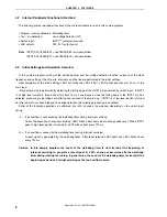
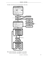
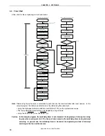
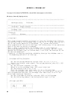
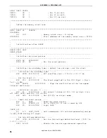
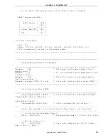
C language program example (same content as in
described above and the sample program)
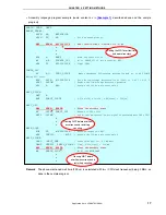
void hdwinit(void){
unsigned char ucCnt200us; /*
8-bit variable for 200 us wait
*/
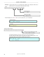
WDTM = 0b01101111;
/*
WDT overflow time = 2^20/fx = 131.07 ms
*/
•
•
•
/*
Check the reset source
*/
ucRESF = RESF;
/*
Read the reset source
*/
if
(ucRESF.4){
/*
A reset generated by WDT
*/
P2
=
0b00000001;
/*
Light LED2
*/
}
if
(!ucRESF.0){
/*
Omit subsequent LVI-related processing during LVI reset
*/
/*
Set low-voltage detection
*/
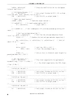
LVIS = 0b00000111; /*
Set the low-voltage detection level (VLVI) to 2.85 V +-0.15 V
*/
LVION
=
1;
/*
Enable the low-voltage detector operation
*/
for (ucCnt200us = 0; ucCnt200us < 9; ucC+){
/*
Wait of about 200 us
*/
NOP();
}
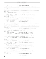
while
(LVIF){
/*
Wait for VDD >= VLVI
*/
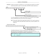
WDTE = 0xAC;
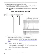
Setting the WDT overflow time
and operation clock
/*
Clear the watchdog timer
*/
}
LVIMD
=
1;
/*
Set so that an internal reset signal is generated when VDD
<
VLVI
*/
}
•
•
•
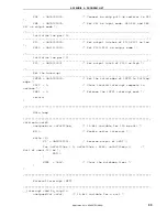
void main(void){
unsigned int unCnt120ms;
/*
16-bit variable for 120 ms wait
*/
EI();
/*
Enable vector interrupt
*/
while
(1){
P2
^=
0b00000001;
/*
Reverse output of LED1
*/
for (unCnt120ms = 0; unCnt120ms < 6666; unC+){
/*
Wait of about 120 ms
*/
NOP();
}
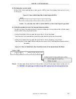
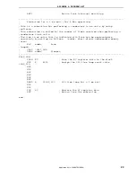
WDTE = 0xAC;
Clearing WDT before
overflow occurrence and
restarting counting
/*
Clear the watchdog timer
*/
}
}
•
•
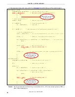
Clearing WDT before
overflow occurrence and
restarting counting
Remark
The above-mentioned wait time (200
μ
s) is calculated with f
CPU
(CPU clock frequency) being 2 MHz, as
done in the sample program.
Application Note U18847EJ1V0AN
18

