APPENDIX A PROGRAM LIST
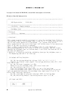
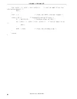
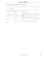
As a program list example, the 78K0S/KB1+ microcontroller source program is shown below.
z
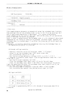
main.asm (Assembly language version)
;*****************************************************************************
;
;
NEC Electronics 78K0S/KB1+
;
;*****************************************************************************
; 78K0S/KB1+
Sample
program
;*****************************************************************************
; Watchdog
timer
;*****************************************************************************
;<<History>>
; 2007.6.--
Release
;*****************************************************************************
;
;<<Overview>>
;
;This sample program presents an example of using the watchdog timer function.
;The overflow time of the watchdog timer is set to 131.07 ms by counting the 8
;MHz fx and runaway detection is performed. (fx: system clock source)
;After completion of the initial settings, LED1 blinks every 120 ms and blinks
;every 60 ms when the switch is pressed.
;Here, a reset is generated by the watchdog timer at a 50% chance of
;occurrence,depending on the timing at which SW is pressed, and LED2 lights,
;because the watchdog timer is cleared about 70 ms after the interrupt of the
;SW input was generated.
;# Normally, an overflow should be avoided by clearing the watchdog timer at
; the beginning and end of an interrupt.
;
;
; <Principal setting contents>
;
; - Set the low-voltage detection voltage (VLVI) to 2.85 V +-0.15 V
; - Generate an internal reset signal (low-voltage detector) when VDD < VLVI
after VDD >= VLVI
; - Set the CPU clock frequency to 4 MHz
; - Select fx as the watchdog timer (WDT) count clock and
; set the overflow time to 131.07 ms
; - Clear the watchdog timer about every 120 ms in the main loop
; - Clear the watchdog timer about 70 ms after the interrupt of the switch
input was generated and clear the watchdog timer about every 60 ms if the
switch input continues thereafter
; - Set the valid edge of external interrupt INTP1 to falling edge
; - Set the chattering removal time during switch input to 10 ms
;
;
; <SW input and LED1>
;
; +----------------------------+
; | SW | LED1 |
; | (P43) | (P20) |
; |-------|--------------------|
Application Note U18847EJ1V0AN
24

