CHAPTER 3 SOFTWARE
3.2 Internal Peripheral Functions to Be Used
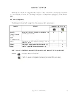
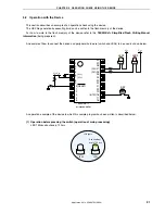
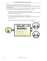
The following internal peripheral functions of the microcontroller are used in this sample program.
•
Program runaway detection: Watchdog timer
•
V
DD
<
V
LVI
detection:
Low-voltage detector (LVI)
•
Switch input:
INTP1
Note
(external interrupt)
•
LED outputs:
P20, P21 (output ports)
Note
INTP1/P43: 78K0S/KA1+ and 78K0S/KB1+ microcontrollers
INTP1/P32: 78K0S/KY1+ and 78K0S/KU1+ microcontrollers
3.3 Initial Settings and Operation Overview
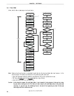
In this sample program, setting of the watchdog timer and low-voltage detection function, selection of the clock
frequency, and setting of the I/O ports, interrupts, and the like are performed in the initial settings.
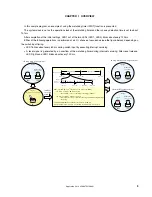
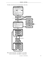
After completion of the initial settings, LED1 out of the two LEDs (LED1, LED2) blinks about every 120 ms, in the
main loop.
Interrupt servicing is performed by detecting the falling edge of the INTP1 pin generated by switch input. If INTP1
is at high level (switch is turned off) after about 10 ms have elapsed since the falling edge of the INTP1 pin was
detected, processing is identified as chattering and returned to the main loop. If INTP1 is at low level (switch is turned
on) after about 10 ms have elapsed since edge detection, the following processing is advanced.
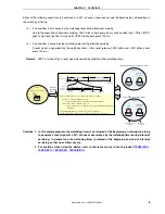
Either of the following operations is performed at a 50% chance of occurrence, depending on the switch input
timing.
<1> If an overflow is not caused by the watchdog timer during interrupt servicing
Due to the execution of interrupt servicing, LED1 blinks about every 60 ms during switch input. When INTP1
goes to high level (switch is turned off), LED1 blinks about every 120 ms.
<2> If an overflow is caused by the watchdog timer during interrupt servicing
A reset signal is generated by the watchdog timer. After reset release, LED2 lights and LED1 blinks about
every 120 ms.
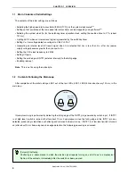
Caution In this sample program, the count of the watchdog timer is not cleared at the beginning of
interrupt servicing to generate a reset signal at a 50% chance of occurrence by the watchdog
timer during interrupt servicing. In general use, the count of the watchdog timer is cleared at the
beginning and end of interrupt servicing so that no overflow occurs.
Application Note U18847EJ1V0AN
8

