2-210
Hardware Installation
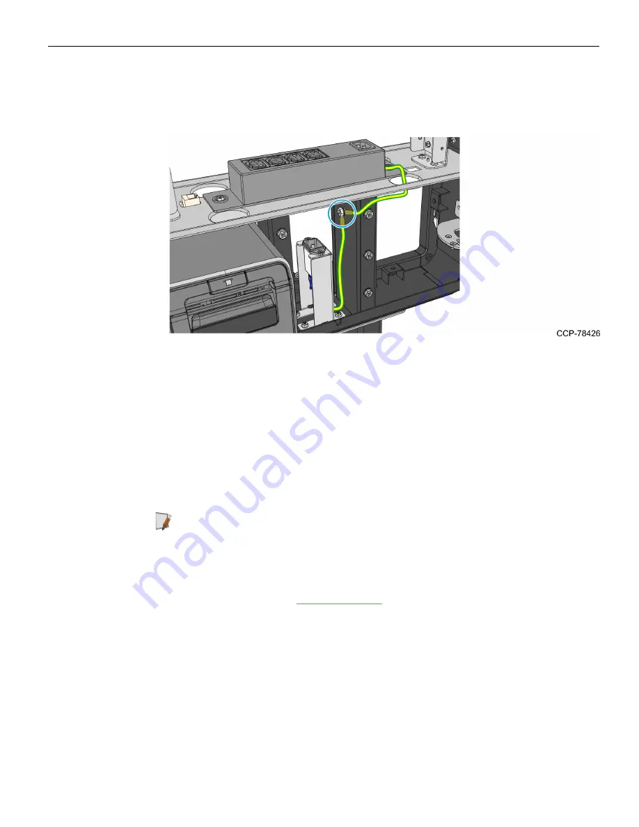
2. Connect the other ends of the Power Strip and the AC Filter ground cables to the
kiosk.
•
Using an M4 screw, secure the ground cables to the right-hand leg mount.
3. Remove the bundled cables from the bubble wrap.
4. Route and connect the internal cables. Refer to the images following this procedure.
a. Insert the bundled cables through the access hole in the Main Frame, but leaving
the LAN Cable on the lower right side of the Main Frame.
b. Secure the bundle with p-loops along its route.
c. If PIN Pad is used as a payment device, route the PIN Pad cable to the Ebox,
following the route of the bundled cables. Secure the PIN Pad cable with six
cables ties along its route.
Note:
A payment device may be an MSR or a PIN Pad. For MSR, the MSR cable
is already bundled and routed together with other internal cables.
d. Connect the Display Power Cable to the Power Strip.
e. Connect the cables to the Primary Terminal. For a complete list of port
assignments, refer to
Содержание SelfServ XK32
Страница 1: ...Installation Guide NCR SelfServ XK32 2247 Kiosk Release 1 0 BCC5 0000 5246 Issue B...
Страница 13: ...Product Overview 1 3 Product Labels...
Страница 14: ...1 4 Product Overview Configurations...
Страница 27: ...Hardware Installation 2 17...
Страница 28: ...2 18 Hardware Installation...
Страница 34: ...2 24 Hardware Installation 4 Mount and secure the Metal Stand Legs on the anchors using four M12 nuts...
Страница 56: ...2 46 Hardware Installation 14 Secure the Indicator Light and Camera cables to the cable clamp on the Top Panel...
Страница 80: ...2 70 Hardware Installation 4 Mount and secure the Metal Stand Legs on the anchors using four M12 nuts...
Страница 135: ...Hardware Installation 2 125 3 Secure the top side of the Signage assembly using an M4 flathead screw on each side...
Страница 141: ...Hardware Installation 2 131 3 Tighten the nuts and make sure that the Wall Bracket is firmly secured to the wall...
Страница 145: ...Hardware Installation 2 135 3 Secure the top side of the Signage assembly using an M4 flathead screw on each side...
Страница 156: ...2 146 Hardware Installation 14 Secure the Indicator Light and Camera cables to the cable clamp on the Top Panel...
Страница 179: ...Hardware Installation 2 169 3 Tighten the bolts and make sure that the Wall Bracket is firmly secured to the wall...
Страница 183: ...Hardware Installation 2 173 3 Secure the top side of the Signage assembly using an M4 flathead screw on each side...
Страница 194: ...2 184 Hardware Installation 14 Secure the Indicator Light and Camera cables to the cable clamp on the Top Panel...
Страница 218: ...2 208 Hardware Installation Single Sided Kiosk with PIN Pad Payment Device...
Страница 222: ...2 212 Hardware Installation Dual Sided Kiosk with PIN Pad Payment Device...
Страница 226: ...2 216 Hardware Installation Dual Sided Kiosk with PIN Pad Payment Device...
Страница 227: ...Hardware Installation 2 217 Port Assignments...
Страница 249: ...Hardware Installation 2 239 5 Close the receipt cover 6 Remove excess paper by tearing it against the Cutter Blade...


