


1-22
|
ni.com
Chapter 1
Getting Started with the cDAQ Chassis
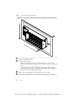
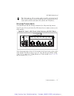
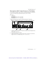
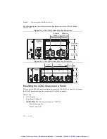
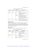
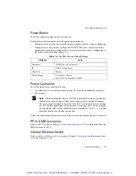
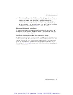
The following figures show the surface mounting dimensions for the cDAQ-9185 and
cDAQ-9189.
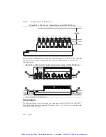
Figure 1-18.
cDAQ-9185 Surface Mounting Dimensions
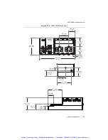
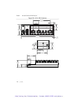
Figure 1-19.
cDAQ-9189 Surface Mounting Dimensions
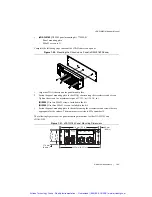
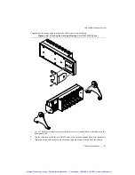
Mounting the cDAQ Chassis on a Panel
You can use the NI 9904 panel mounting kit to mount the cDAQ-9185 on a panel. You can use
the NI 9905 panel mounting kit to mount the cDAQ-9189 on a panel.
What to use:
•
cDAQ chassis
•
Screwdriver, Phillips #2
•
(cDAQ-9185)
NI 9904 panel mounting kit, 779097-01
–
Panel mounting plate
–
M4x25 screws (x2)
NI CompactDAQ
NI cDAQ-9185
POWER
STATUS
PFI 0
RESET
DO NOT SEPARATE
CONNECTORS
WHEN ENERGIZED
IN HAZARDOUS
LOCATIONS
2
1
ACTIVE
4
3
INPUT
9-30 V
16 W MAX
47.24mm
(1.
8
600 in.)
46.96 mm
(1.
8
4
88
in.)
41.14 mm
(1.6197 in.)
3
0.5
8
mm
(1.2040 in.)
LINK/
ACT
10/100/
1000
1
2
LINK/
ACT
10/100/
1000
SYNC
NI CompactDAQ
NI cDAQ-9189
POWER
STATUS
PFI 0
RESET
DO NOT SEPARATE
CONNECTORS
WHEN ENERGIZED
IN HAZARDOUS
LOCATIONS
2
1
ACTIVE
8
7
6
5
4
3
INPUT
9-30 V
16 W MAX
LINK/
ACT
10/100/
1000
1
2
LINK/
ACT
10/100/
1000
SYNC
47.2 mm
(1.
8
6 in.)
3
0.
8
mm
(1.21 in.)
47.0 mm
(1.
8
5 in.)
41.1 mm
(1.62 in.)
94.5 mm
(
3
.72 in.)
Artisan Technology Group - Quality Instrumentation ... Guaranteed | (888) 88-SOURCE | www.artisantg.com


