


6-32
|
ni.com
Chapter 6
Counters
Frequency Output can be routed out to any PFI terminal. All PFI terminals are set to
high-impedance at startup. The FREQ OUT signal also can be routed to many internal timing
signals.
In software, program the frequency generator as you would program one of the counters for
pulse train generation.
For information about connecting counter signals, refer to the
Default Counter/Timer Routing
section.
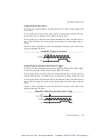
Frequency Division
The counters can generate a signal with a frequency that is a fraction of an input signal. This
function is equivalent to continuous pulse train generation. Refer to the
Continuous Pulse Train
Generation
section for detailed information.
For information about connecting counter signals, refer to the
Default Counter/Timer Routing
section.
Using the Watchdog Timer
You can use the watchdog timer for counter output operations. Refer to the
Watchdog Timer
section of Chapter 1,
Getting Started with the cDAQ Chassis
, for more information.
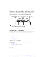
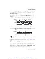
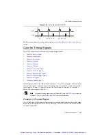
Pulse Generation for ETS
In the equivalent time sampling (ETS) application, the counter produces a pulse on the output
a specified delay after an active edge on Gate. After each active edge on Gate, the counter
cumulatively increments the delay between the Gate and the pulse on the output by a specified
amount. Thus, the delay between the Gate and the pulse produced successively increases.
The increase in the delay value can be between 0 and 255. For instance, if you specify the
increment to be 10, the delay between the active Gate edge and the pulse on the output increases
by 10 every time a new pulse is generated.
Suppose you program your counter to generate pulses with a delay of 100 and pulse width of 200
each time it receives a trigger. Furthermore, suppose you specify the delay increment to be 10.
On the first trigger, your pulse delay will be 100, on the second it will be 110, on the third it will
be 120; the process will repeat in this manner until the counter is disarmed. The counter ignores
any Gate edge that is received while the pulse triggered by the previous Gate edge is in progress.
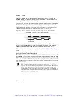
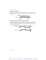
The waveform thus produced at the counter’s output can be used to provide timing for
undersampling applications where a digitizing system can sample repetitive waveforms that are
higher in frequency than the Nyquist frequency of the system. Figure 6-36 shows an example of
pulse generation for ETS; the delay from the trigger to the pulse increases after each subsequent
Gate active edge.
Artisan Technology Group - Quality Instrumentation ... Guaranteed | (888) 88-SOURCE | www.artisantg.com


