© National Instruments
|
I-1
Index
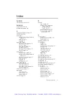
Symbols
<20 MHz source mode, 6-39
Numerics
10/100/1000 LED, 1-29
80 MHz source mode, 6-39
A
acquisitions, digital waveform, 5-2
ACTIVE LED, 1-29
analog input
getting started with applications in
software, 3-7
timing signals, 3-1
triggering, 3-1
analog input signals
AI Convert Clock behavior, 3-2
AI Pause Trigger, 3-7
AI Reference Trigger, 3-5
AI Sample Clock, 3-2
AI Sample Clock Timebase, 3-2
AI Start Trigger, 3-4
analog output
data generation methods, 4-1
getting started with applications in
software, 4-7
glitches on the output signal, 4-7
timing signals, 4-3
triggering, 4-3
watchdog timer, 4-7
analog output signals
AO Pause Trigger, 4-5
AO Sample Clock, 4-3
AO Sample Clock Timebase, 4-4
AO Start Trigger, 4-4
ANSI C documentation, A-3
applications
counter input, 6-3
counter output, 6-24
edge counting, 6-4
arm start trigger, 6-3
B
buffered
edge counting, 6-4
hardware-timed generations
analog output, 4-2
digital output, 5-9
position measurement, 6-21
two-signal edge-separation
measurement, 6-23
C
C Series module
parallel versus serial DIO, 1-36
specifications, A-2
cascading counters, 6-38
cDAQ chassis
diagram, 1-1
features, 1-28
installation and configuration, 1-4
mounting, 1-15
reserving in MAX, 1-14
troubleshooting device
connectivity, 1-28
unpacking, 1-3
using, 1-35
cDAQ module interface, 1-36
channel Z behavior, 6-20
chassis grounding screw, 1-28
choosing frequency measurement, 6-15
configuration, 1-4
connector power, 1-31
continuous pulse train generation, 6-27
controlling counting direction, 6-4
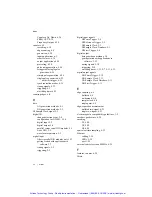
counter signals
Counter
n
A, 6-36
Counter
n
Aux, 6-35
Counter
n
B, 6-36
Counter
n
Gate, 6-34
Counter
n
HW Arm, 6-36
Counter
n
Internal Output, 6-37
Counter
n
Source, 6-33
Counter
n
TC, 6-37
Artisan Technology Group - Quality Instrumentation ... Guaranteed | (888) 88-SOURCE | www.artisantg.com

